Photos and Features
After getting the SeeMeCNC Rostock MAX v3 all built I cleaned up the mess I made in the office and took a few photos of the printer before diving into prints. This way I could take a look at a few of the details on the v3 that are new and different and also to see just how different it is from the Eris. Before diving into that I wanted to touch on a few different points for those of you who are completely new to 3D Printing. First, you should check out my visit to SeeMeCNC article where I take a look at their offices and also do a brief rundown on how 3D Printing works as well as talk a little bit about Delta printers and RepRap.
For a quick bit of history and information on the Rostock Max. The Rostock MAX is based on the original Rostock design from the RepRap community. SeeMeCNC built on that design with their original MAX design that they sold through their Indiegogo campaign. From there they evolved that design into the v2 a few years ago and then a few months ago to the v3. Being a RepRap based device they have a big focus on the open source community, so all of the v3 designs are shared with the community just like the previous models.
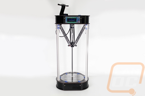
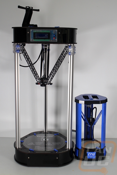
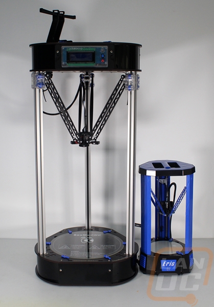
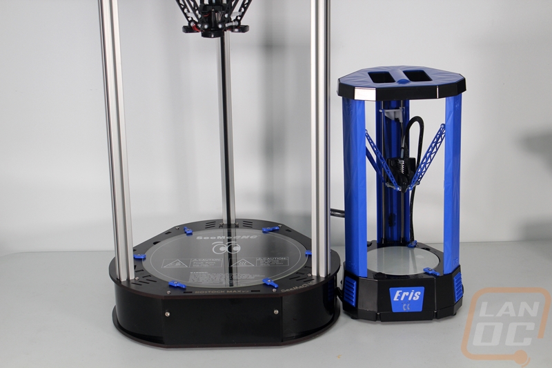
So the Rostock MAX v3 is really hard to even put to scale in photos, so I took a couple pictures of it with the SeeMeCNC Eris. As you can see, the v3 dwarfs the Eris with its almost 42-inch height (including the spool holder), in fact, the Eris is just a touch too high to fit in the v3’s overall build area. The v3, like the v2, before is constructed from laser cut melamine wood in the top and bottom sections with three aluminum t-slot extrusions for the towers. The Eris, on the other hand, is almost completely injection molded with just a few round metal pillars for tower stability. The v3 does incorporate a lot more injection molding than the v2, but we can’t really see them from the outside.
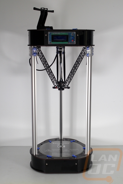
The MAX design has two enclosed areas, one at the top of the printer and the other at the bottom. With the v2 almost everything was down in the bottom of the printer but the v3 has moved everything up to the top to save on build time. Because of this, the LED screen is now up top on the front where before it was on the bottom. That said, SeeMeCNC did configure the v3 to be able to build the old way with the Rambo and controller down on the bottom as well if you would prefer that way but the build instructions only show the new layout.
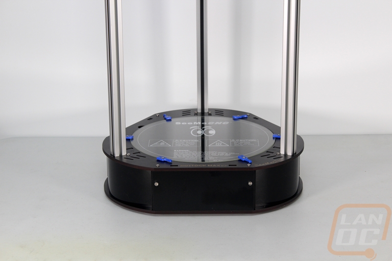
SeeMeCNC kept branding simple and to the point with the v3, letting the delta design that they are the biggest name in do most of the talk. Down on the bottom around the heated bed, they did etch the Rostock MAX v3 branding as well as the SeeMeCNC name as well. A pair of their signature eyes would have been cool as well.
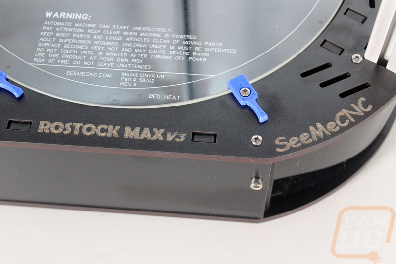
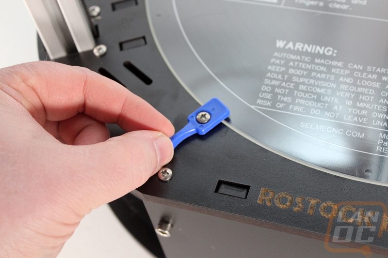
One of the new features on the v3 was actually old news to me as a heavy Eris user. They dropped the Borosilicate glass print surface down into the base where the v2 had the glass up top clipped on with metal binder clips. They did this with an injection molded plate inside the base, injection molded mounts for It to sit on, and then everything is held together with bolts running through the new hold downs into the mounts inside. The new hold down are blue plastic and rotate to let you lift the glass up and out if needed. This lets you have access to the new thinner Onyx heatbed. This is very similar to the Eris’s floating bed, even having the exact same hold downs.
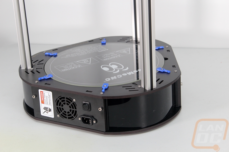
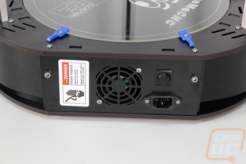
The new flipped design means the power supply is mounted down in the base. Once you get everything wired up, you have a standard PC plug for the power connection, an on/off switch, and the bases only cooling fan all in one panel.
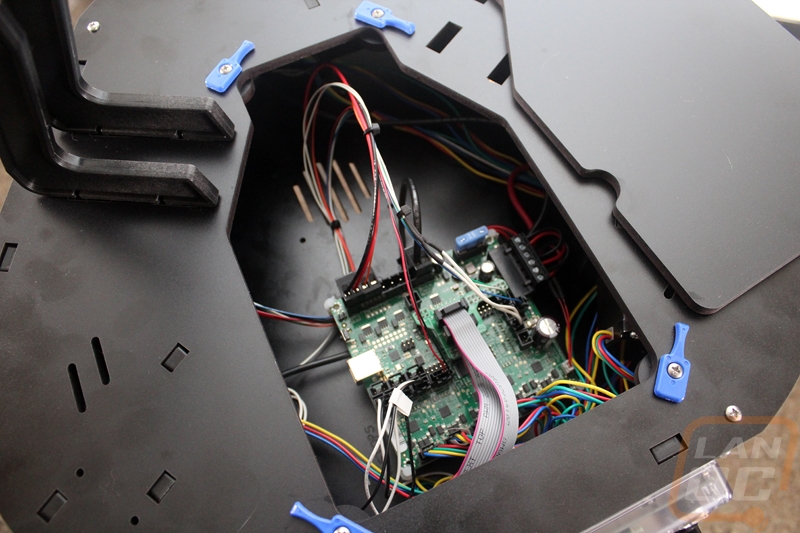
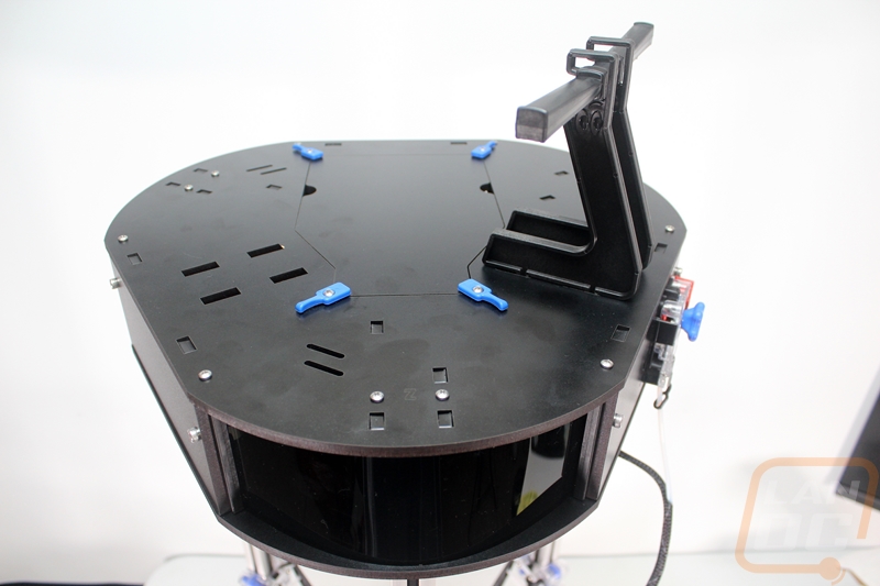
Up top, the v3 has the same rounded triangle shape of the base but rather than the floating heatbed the top has a removable panel to give us access to the inside. Directly under the opening is the Rambo control board, but you can also partially get at the four stepper motors from here. The v3 also supports installing a Raspberry Pi next to the Rambo to access and run your printer using remote software like Octoprint. By doing this you can put the printer in another room but send prints to it and if you install a camera you can also keep an eye on your print status.
The top access panel has the same blue hold downs keeping it in each corner. Beyond that, up top, we have a slide on double spool holder directly above the extruder. The top section is actually designed to support adding a second extruder including another spool holder over on the left side to match the one on the right for people who add a dual extrusion setup to their v3.
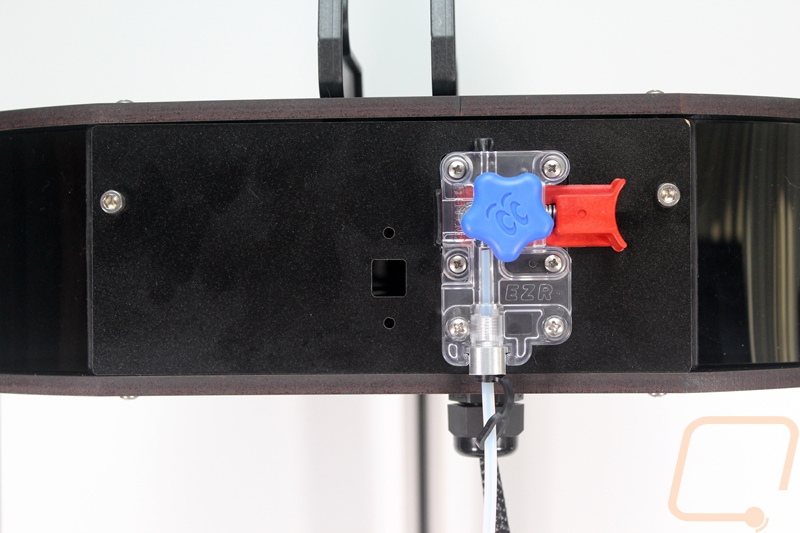
For the extruder, SeeMeCNC redesigned their already popular EZStruder to the new EZRStruder. The old design was used on the v1, v2, and the Eris and had a spring-loaded lever design that puts pressure onto the filament into the extruder gear. The lever design makes removing filament or installing new filament easy and avoids damage to the stepper. The new design is a little more compact and does the same thing only it now has better support around the filament before and after the gear. This makes loading easier and also helps with support for flexible filaments.
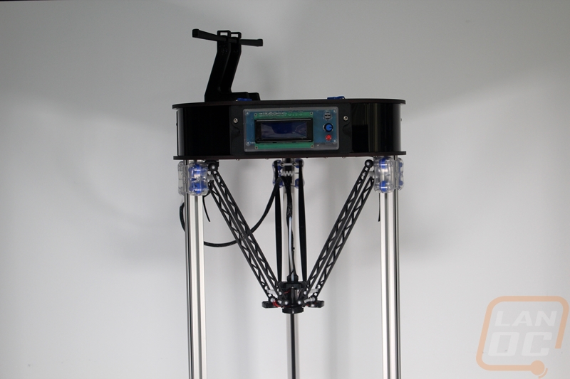
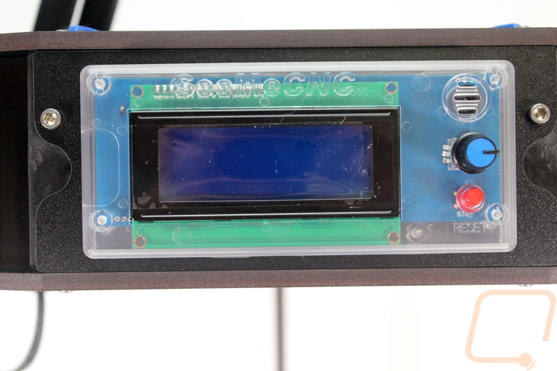
On the front panel, the v3 has a control panel. The LCD is 20 characters wide and 4 rows tall and it all packs into a transparent injection molded case with a reset button, speaker for notifications, and a knob that also pushed down for a click. This is the one part of the v3 that really looks out of place but is obviously extremely important. I would love to see a little tighter integration with it all being flush mounted preferably into a bolt on panel rather than having two independent designs attached to each other. The screen itself is enough to get the job done and it does have the SD card interface on the left side but a lot of the other manufacturers are quickly jumping into color displays with more modern navigation. I know that SeeMeCNC has brought on a software developer and they are working on big improvements in this exact area, so I’m sure we will see improvements in the future and I can’t wait!
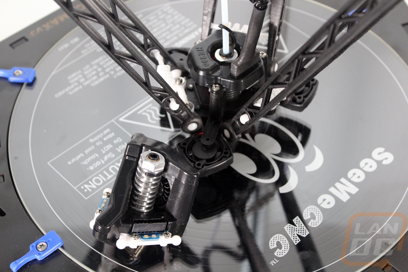
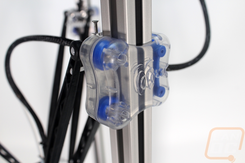
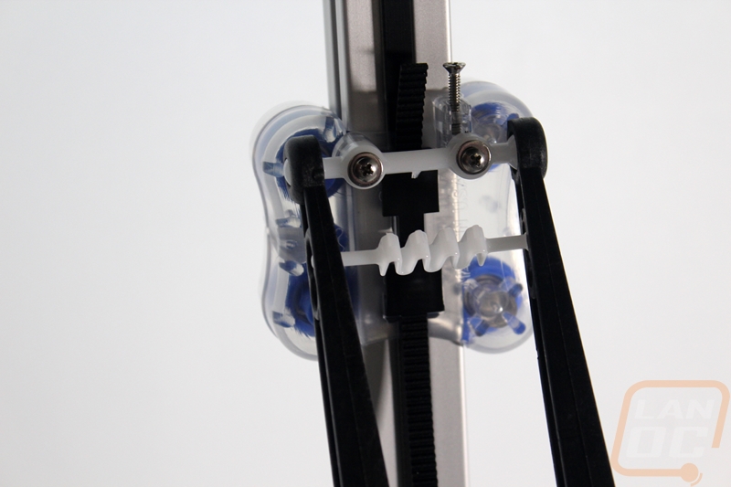
In between the top and bottom of the v3 are the three towers, the hot end, and the overall build area. This is the area that you are going to see all of the time. This is also where a couple big changes happened. First off the hotend is a completely new design, but before I get into that I did want to point out the injection molded cheapskates that bring everything together to move the hotend. These were actually introduced in September of 2015 so they came out after the v2 but before the v3. This happens a lot with SeeMeCNC, they don’t hold back changes and innovations for the next model, they brought these out and just included them with the v2 kits made after September 2015. Anyhow, I love the design, the have two transparent outer casings that hold four wheels with ball bearings in place. There are two wheels per side of the t-slot extrusions and they run perfectly in the track. One side has a suspension to keep the grip tight as well. From there they attach to the belt with a clip and they use ball sockets for the six (total) arms. A small plastic spring keeps the arms tight and straight and the same arms attach to the hot end the same way.
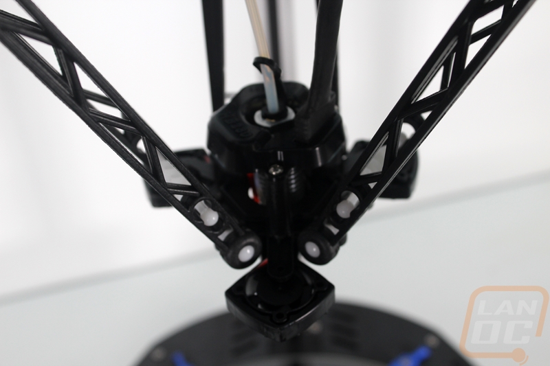
So beyond the frame improvements that make building the v3 easier, the cheapskates, and the ability to now add your Pi inside, it’s really the new HE280 hotend that makes the v3 so different. SeeMeCNC took the knowledge they learned with design and implementation of the automatic leveling on the Eris and introduced bed leveling on the v3. The leveling is a huge improvement as leveling delta printers is a lot more difficult. They managed to do it all without any extra moving parts, using an accelerometer on the PCB to pick up when the tip of the hotend touches the print surface as it taps around checking multiple spots. The new hotend is officially listed as an all metal design though some people will argue that it isn’t completely all metal with the PTFE tube still running down to the heatbreak. The new design also went with a heating cartridge that uses a thermal fuse for safety.
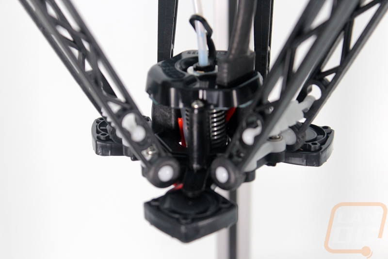
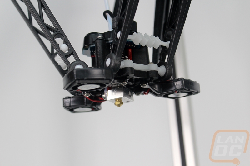
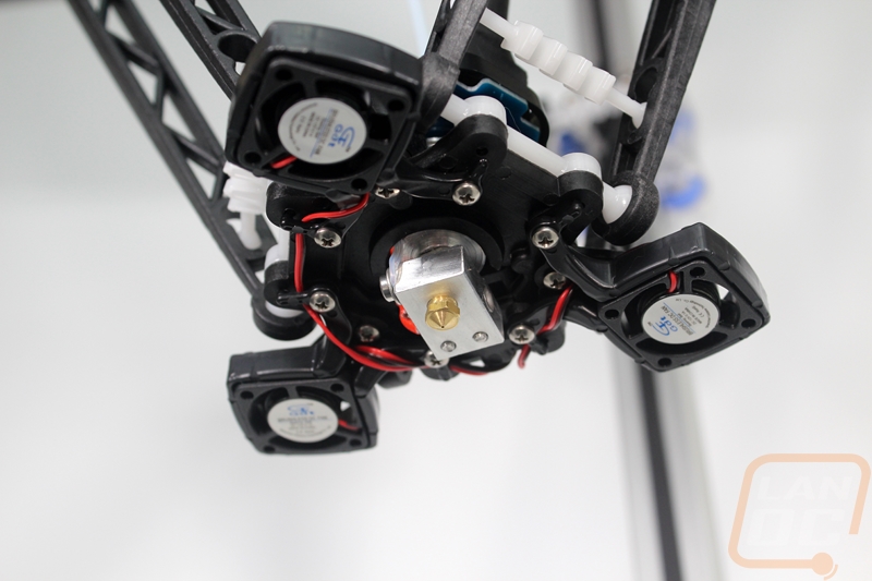
Just for comparison, I did grab one of the hotends for an Eris just to give a little scale. The three cooling fans make most of the difference, but even then there is a little more to the frame of the v3’s hotend where the Eris hotend is a little simpler. Both hotends have the same HE280 designation. This is a little confusing, but from what I can tell the actual metal part of the hotend is just about the same except the room they made for the thermal fuse. The PCB that houses the accelerometer is also the same, but it is now mounted up at the top of the heatsink to better keep it away from the heat. Beyond that the HE280’s from the Eris and v3 are completely different. The v3’s framing is larger and more robust and the v3 has three additional fans mounted to it facing down for part cooling where the Eris’s hotend used the one fan across the heatsink to also blow air at the nozzle.