Board Layout and Pictures
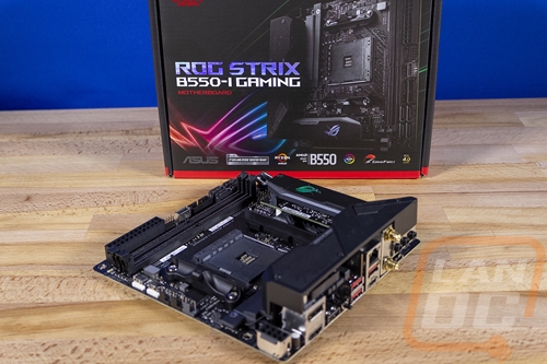
If it wasn’t clear with the model name, the Asus ROG Strix B550-I Gaming is Asus’s only B550 Mini ITX board. So the B550-Ihas that 6.7 inch by 6.7-inch form factor. Packing features into that small form factor can be a challenge but at this point, Asus has become very good at it. For the B550-I they have integrated one section of breakout boards down above the PCIe slot. Beyond that, they have tried to keep most things still around the outside edge.
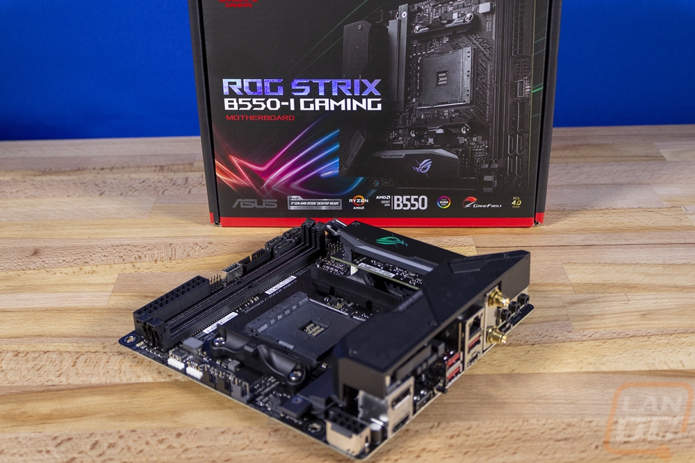
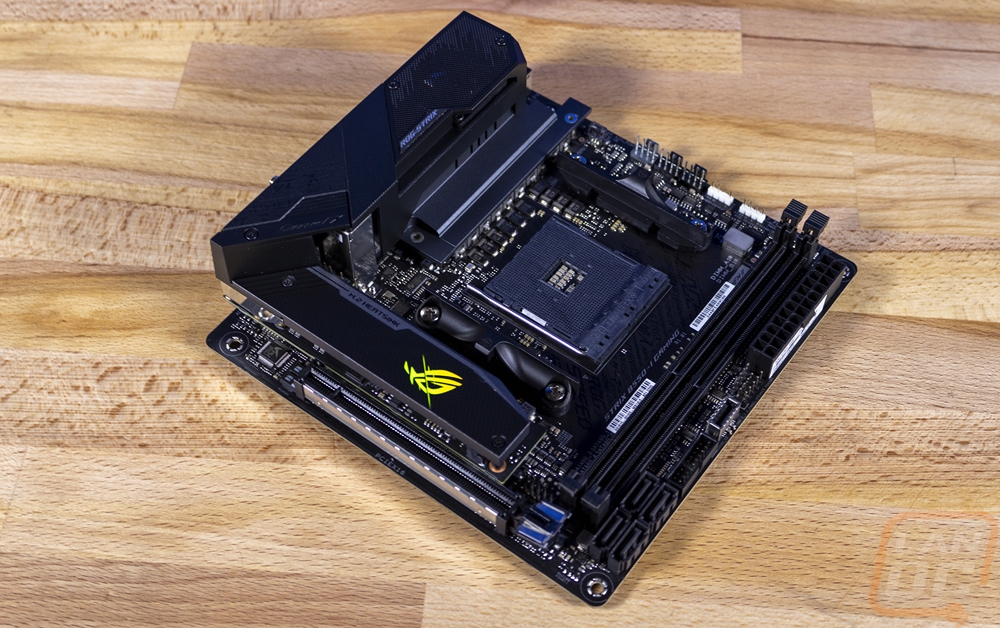
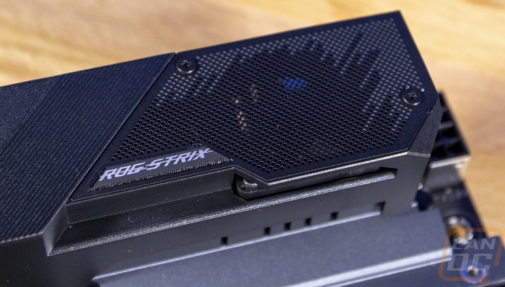
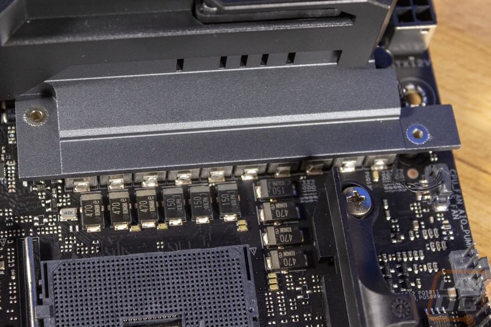
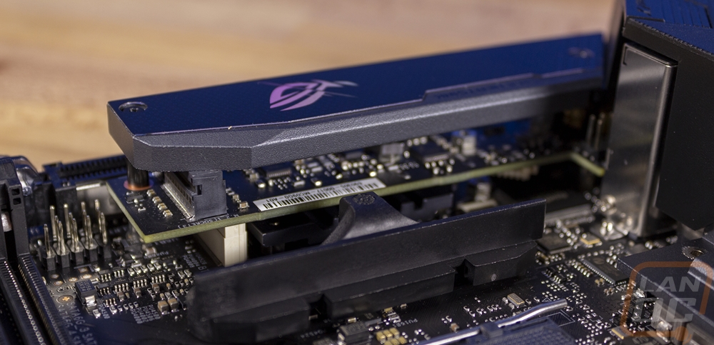
For the VRMs, Asus went with an 8+2 configuration which is all lined up on the left of the CPU socket. This area still looks very open and this is because you don’t see any of the cooling that would normally be around the CPU socket. Because of the tight space, they moved things around to leave room to put things along the top edge of the board and to keep heatsink clearance open as possible. So the 8.2VRMs have a heatsink bolted down on top of them and the heatsink itself is offset and runs up under the rear I/O cover. The I/O cover looks great and is all black with a mesh area on the top half. This is because there is a small fan integrated for the active cooling of the VRMs.
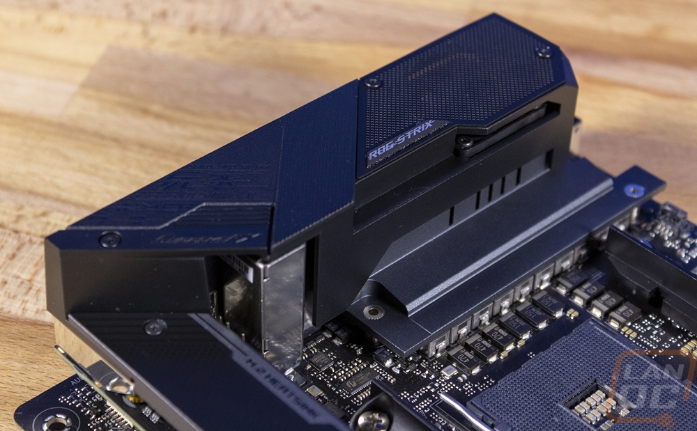
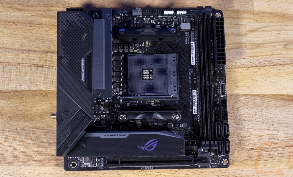
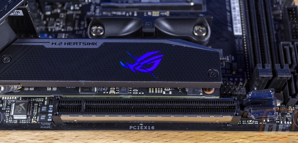
The other half of the cooling is the M.2 heatsink which consists of a thick aluminum panel that goes over top of the M.2 on the top side of the board. It doesn’t have fins but it does use a thermal pad to soak up at least some of the heat generated. This view also gives us a good look at the breakout board that Asus uses which packs in under the CPU socket and above the PCIe slot and fits the M.2 and the onboard audio as well.
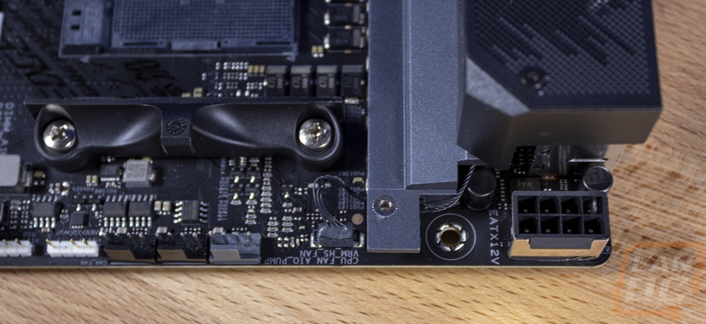
Okay, so I like to work my way around the board to see what features are visible. Starting in the top left corner you can see the 8-pin CPU power in the farthest corner which has a metal cover around it along with thicker pins which is Asus’s ProCool II tech as they call it. You can see the wire and connection for the VRM fan and then next to that there are three 4-pin PWM fan headers. The grey one is for the CPU fan, the middle is labeled for an AIO coolers pump, and then the end plus is for a chassis fan. Ignoring any other fan headers on the board, three is still more than a lot of ITX boards get in total!
In the top right corner, you can see the fan headers I previously mentioned. Then next to those there are two white plugs. Those are both RGB headers. One is a three-pin addressable RGB header and the other is a traditional RGB header with four pins. Next to that, they have used the open space to print the front panel connector layout, which might be confusing for some because that header isn’t in this area, but it is nice it is included at all. Next to that, four small surface mounted LEDs show boot status and help pinpoint boot issues if something fails.
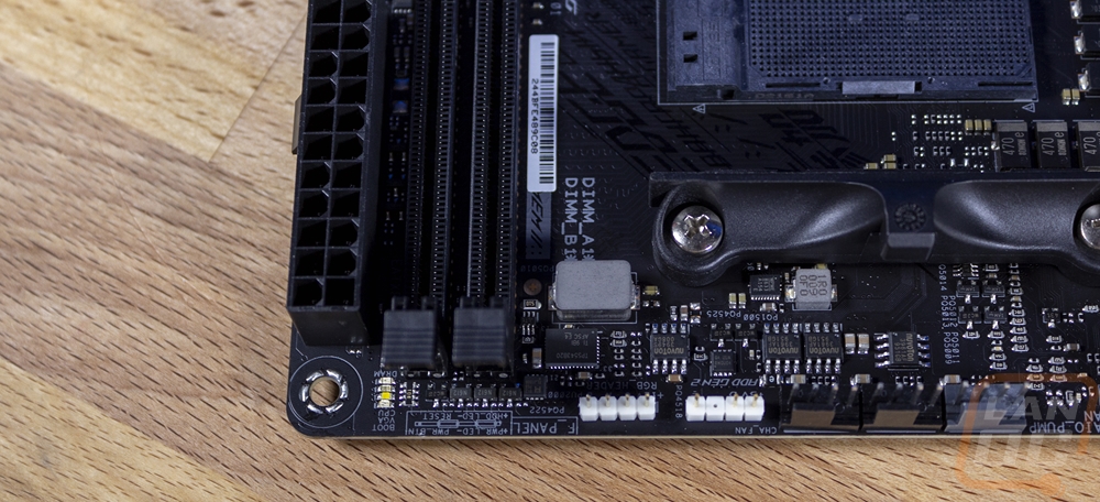
The right edge of the B550-I is the main home for all of the connections and this is nice because you should still be able to get at this area even when installed to a point. The two DDR4 slots run the whole length as well and they have the signature Asus clips on top only. Starting at the top you have the 24-pin motherboard power. Then right below that is the front panel header which we found the labels for up on the top edge. The front speaker is right above that header as well. Then you have a new style USB 3.2 Type-C front panel connection as well as a normal USB 3.2 front panel header. Then down at the bottom, there are four SATA headers as well.
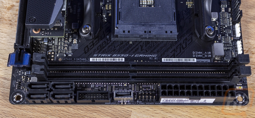
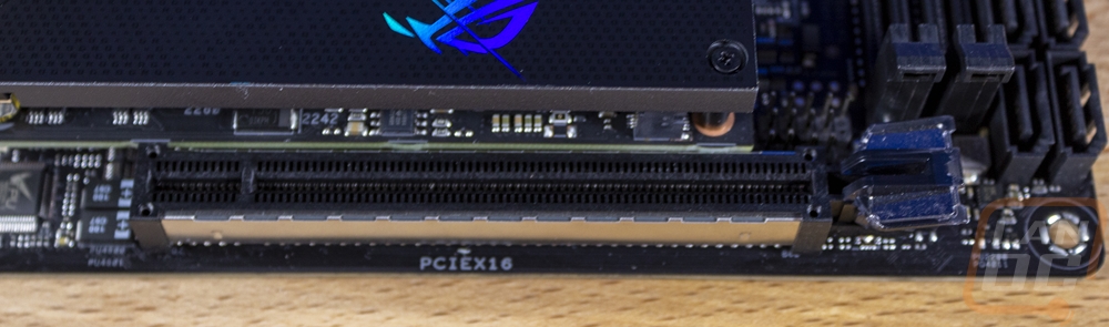
The bottom of the B550-I is dominated by the PCIe slot at the bottom and it has a few things going on. The big one is that this is PCIe 4.0 and being the only slot it gets full x16 bandwidth. The slot has metal shielding around it which is soldered down into the PCB to give it more shear strength to hold your heavy video card. If you look closely you can also see that just above the slot lock Asus also slipped in a USB 2.0 header as well down in this area.
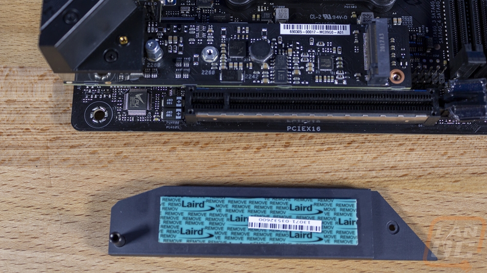
I spoke about the M.2 heatsink previously but here you can get a better look at it with it off. But we can also talk about how the M.2 slot is also a PCIe 4.0 slot and it has x4 bandwidth.
The rear I/O is unique for the B550-I for a few different reasons. I honestly thought that the cover would come pre-installed so that was a bummer. Most other boards have been starting to integrate that and ti makes the installation of the board a little easier. But because of the integrated VRM cooling and fan in the rear I/O area and the riser card, down at the bottom the I/O looks weird. So on the far left, you have DisplayPort and HDMI connections if you are running a CPU with onboard video. Next to that is a traditional USB 2.0 plug that also doubles as the BIOS flashing port. Directly next to that, the tiny button is the button for that. There are then three red USB ports which are all SuperSpeed 10 or USB 3.2 Gen 2. There are a limited number of USB ports in total, but other than the one USB 2 port the others are all high speed. There is also a Gen 2 Type-C port as well. For the LAN Asus went with the always reliable Intel NIC which might seem a little weird on an Asus board. But this is the same I225-V 2.5Gb Ethernet that is included with Z490 chipset board and it gets you a bump in performance over 1G but isn’t as fast as the high-end 10G NICs. There are two antenna plugs for the AX200 WiFi 6 NIC. Then the audio gets weird again with just three audio connections. You have a line in, line out, and microphone in. Then below that, the Type-C is the main audio connection and Asus included an adapter cable for it. You can see how all of those are laid out horizontal because they are on the raised PCB.
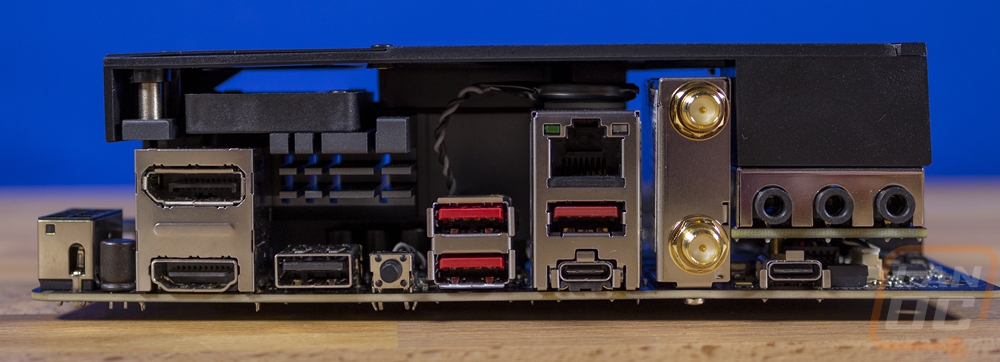
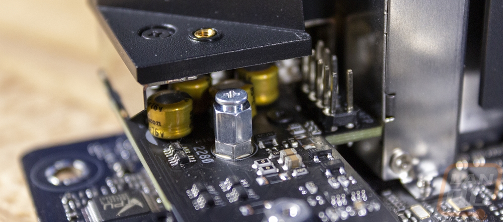
Speaking of the raised PCB, if you look closely you can see how Asus tucked the caps up under everything and the front panel audio header is also right next to them. That is going to be a pain to plug in for sure!
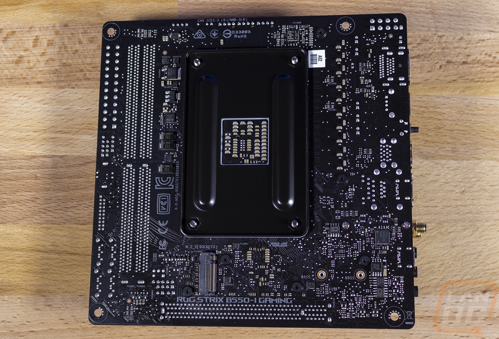
The back of the B550-I mostly just reinforces just how packed everything is on the board with even the back being covered. You can see that they did slip in another M.2 slot down under the CPU socket. This is also PCIe 4.0 and running at x4 which is nice. Both slots support SATA M.2 drives as well so there shouldn’t be any confusion there.