Board Layout and Pictures
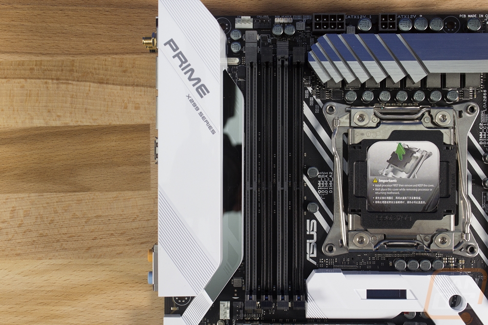
You most likely have seen Asus Prime boards before now, but if this is your first time Asus goes a different direction for the Prime boards when compared to their Strix, ROG, and TUF lines. Most of those are flashy and all blacked out but with Prime boards, they keep the styling simpler and they use white and shades of gray along with black. The Prime X299 Deluxe is a full ATX board that is 12 inches tall and 9.6 inches wide. It is the flagship Prime board in a series of Prime X299 boards. X299 itself is a higher end platform as a whole but with this being on the higher end of that, it is completely packed with features so let's see if we can get through them all.
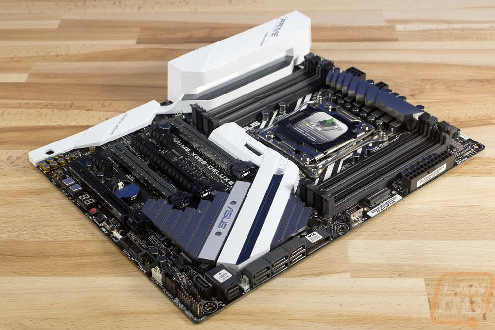
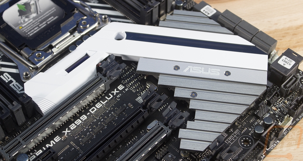
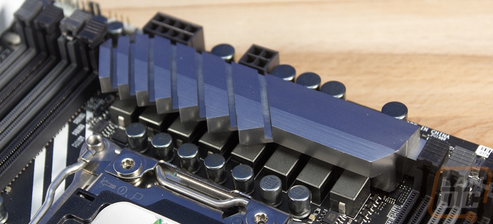
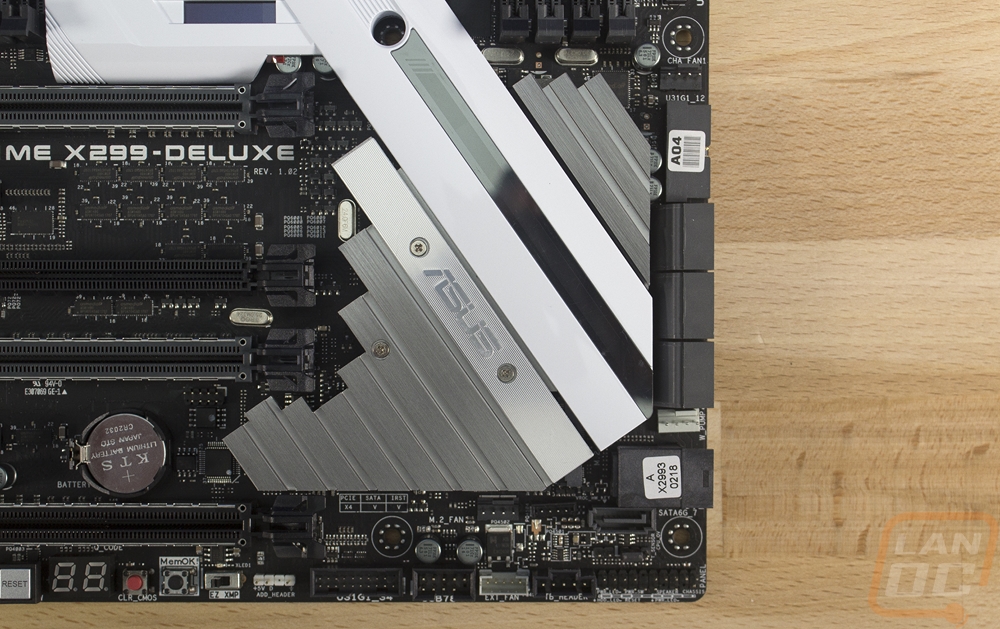
For cooling the board has two main heatsinks. There is a large low profile heatsink down next to the PCIe slots that covers and cools the X299 chipset then the second up above the CPU that keeps the power circuitry cool. The power heatsink fits in between the two sections of ram DIMMS and it is just barely wider than the CPU socket. It has an angled design and is machined out of aluminum and finished with a gray anodized finish. With everything going on the board it blends into the background. The chipset heatsink, on the other hand, is large and very visible. Part of that is because of the white finish in the middle with a mirrored stripe up the middle. The stripe has Asus Aura lighting behind it when it is powered on. There is an Asus logo and then it has multiple steps in the same anodized gray finish as the other heatsink. The chipset cooler’s bottom left portion has a screw then you can remove and it will give you access to one of the two M.2 slots on the board. This one is a little hidden but you still get full x4 bandwidth.
This is also where you will find the new LiveDash. The small black block in the cover just above the PCIe x16 slot is a small OLED screen. This screen displays temperatures, frequencies, fan speeds, error messages, and it also shows boot information when booting.
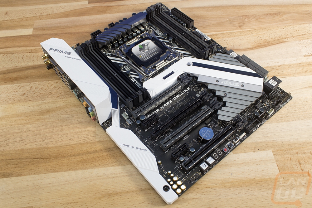
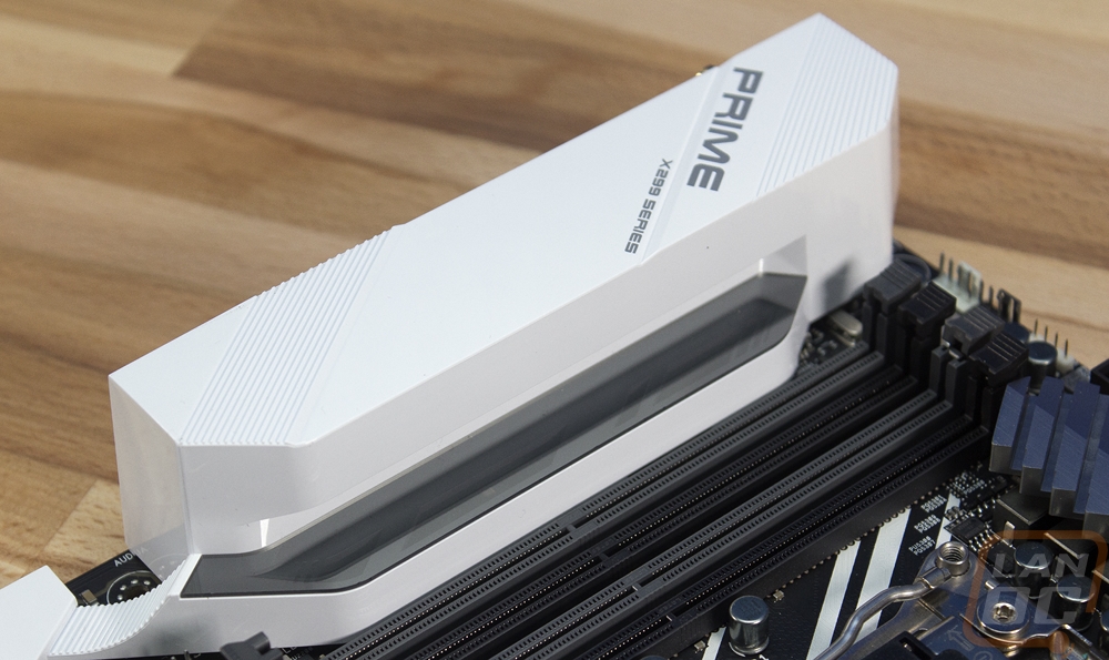
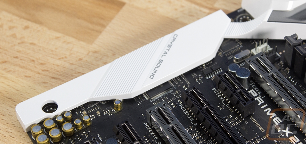
The white theme carries over to the covers over the rear I/O and the audio chipset. Initially, I wasn’t sure if I would like all of these I/O covers because I prefer to see the actual board but when it comes to the rear I/O I always prefer a cover. The rear I/O connections never blend in with a black PCB, not that the all white cover on this board blends in either. But it does look good while being simple. The cover also has Asus Aura lighting integrated into the small space between it and the ram DIMMS. As for the audio shield, I prefer these to be metal but this plastic one may have foil under it. It covers up part of the Realtek ALC S1220A 8 channel audio chipset. They have impedance sensing headphone amps built in and the Japanese capacitors are visible to round things out.
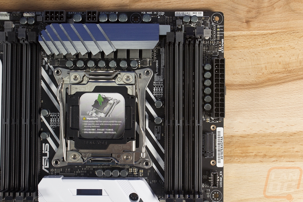
So starting up in the top left region on the board the main things going on here is the rear I/O panel on the left, the CPU socket on the right, and in between four DDR4 DIMMS that are half of the 8 total on the board. That said if you look closely you can see a few other things. Just below the I/O and just above the RAM slots, there are a total of three 4-pin fan headers. The two up top are for the CPU cooler or a water cooling pump and the one down below is one of many case fan headers. Then for CPU power, there is an 8-pin header with a four pin next to it for additional power. Last but not least there is a small white header for RGB lighting that can be controlled via Asus Aura.
On the top right, the second batch of DDR4 DIMM slots are to the right of the CPU socket. Up in the top right corner just below one of the mounting holes there is a row of LED lights. These show the part of the boot process you are on so if your PC locks up mid boot it will help point to what the issue is. Each LED has a description printed on the PCB next to it. Oddly enough the new OLED screen on the Deluxe also shows this same information, I’m not sure that these are needed with that and a LED readout. Below the LEDs is a 24-pin motherboard power connection. The plug below that might not even be recognizable to some people. This is an M.2 that plugs in and sits vertically. Asus included a mounting bracket and screws to attach it. The connection runs at x4 so this is a fast connection and the vertical orientation helps with keeping the drive cool by keeping it away from the CPU and GPUs while letting airflow get to both sides. Then a half inch farther down the board is the new USB 3.1 internal header. Right now there aren’t many cases that support it, but when they do it will be much easier to use than the current USB 3.0 connection while adding faster speeds and Type-C connections.
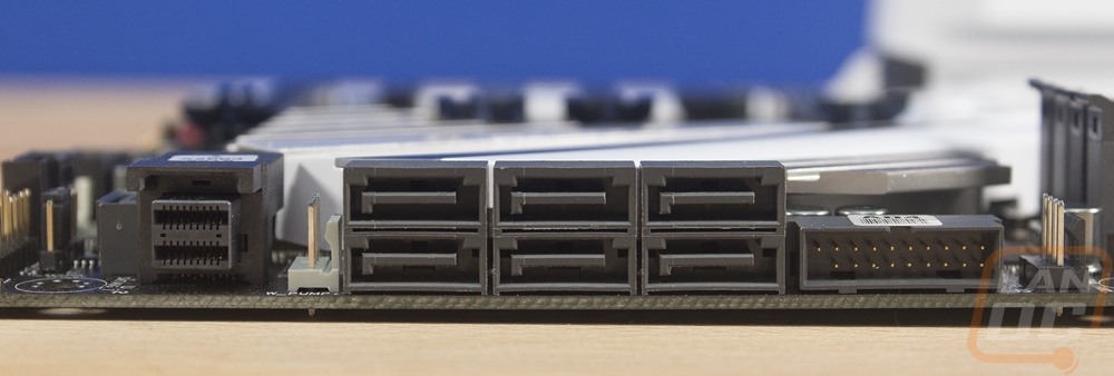
Moving down the right side the chipset heatsink and the M.2 heatsink take up most of the space in this area but that doesn’t mean there isn’t anything going on. There are two 4-pin fan headers along the right edge and then another just under the heatsink. Then there is an older style USB 3.1 header that is positioned at a right angle for better wire management. Below that there are six SATA 3 connections and a new U.2, all right angled as well. The U.2 is similar to M.2 but for an external drive but right now there aren’t many options other than the Intel 750 Series U.2 drive. Just past the U.2, there is one more SATA plug as well. From there we really get into all of the different connections. There is another USB 3.1 header only for some reason this one isn’t listed at all in the specifications and next to it yu have one of the two USB 2.0 headers. The white ext_fan connection is where we hook the included breakout board for the four additional fan headers and the three thermal sensors. Then down in the corner are all of the front panel connections. Over towards the left, there is another RGB header only this one isn’t the standard type, it is a digital header for individually controlled LEDs.
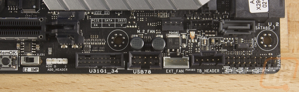
Moving across the rest of the bottom edge there is an EZ XMP switch to avoid having to get into the BIOS at all to turn on a basic XMP mode to clock your ram at its suggested settings and next to it you have a few more buttons. The MemOK button helps when you have memory issues, pressing it will downclock the memory until your PC can boot properly so you can get into the BIOS and adjust the ram to something that works. If that doesn’t do the job the clear CMOS button is right there in bright red. From there you have a LED diagnostic readout and large power and reset buttons. Last but not least the soundcard on the left has its front panel audio connection right along the bottom edge.
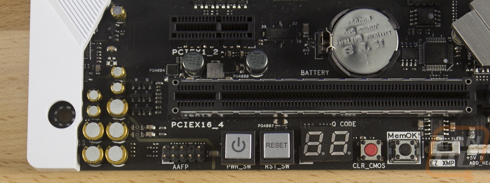
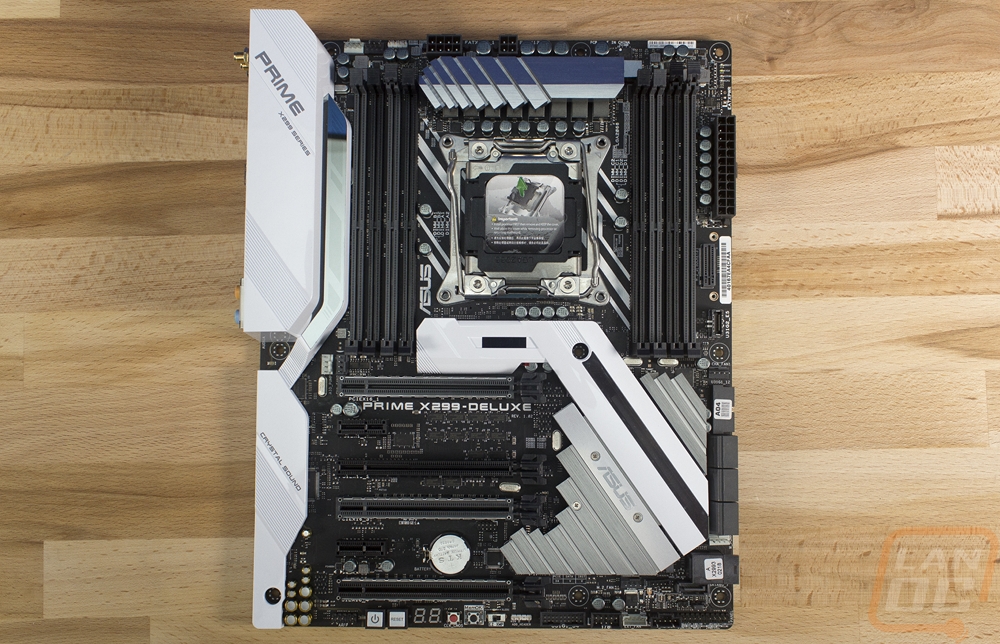
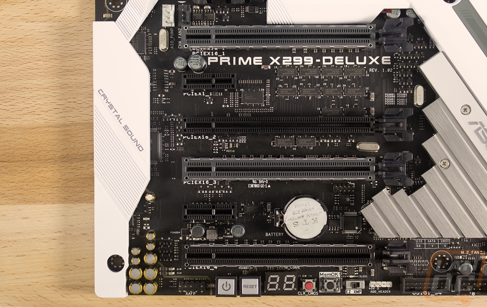
For PCIe slots, officially you get four x16 length slots with three of those having the metal shielding on them and two being gray and spaced in a way to give two full slots in between them. Then there are two PCIe x1 slots just under the two gray slots. Of course, the slot speeds get more complicated depending on what CPU you are running. The high end 7900X has a full 44 lanes but moving down the stack you get 28 lanes on some of the middle CPUs and only 16 for the two Kaby Lake CPUs. To accommodate this here is the PCI breakdown. If you have 44 lanes you are good to do anything you want, 28 is good for two video cards and two slower slots, and 16 lanes slows things down more but you do still get dual x8 slots just like a Z270 boards basically.
44-Lane CPU-
3 x PCIe 3.0/2.0 x16 (x16, x16/x16, x16/x16/x8)
1 x PCIe 3.0/2.0 x16 (max at x4 mode)
28-Lane CPU-
2 x PCIe 3.0/2.0 x16 (x16, x16/x8)
2 x PCIe 3.0/2.0 x16 (max at x4 mode)
16-Lane CPU-
2 x PCIe 3.0/2.0 x16 (x16 or dual x8)
2 x PCIe 3.0/2.0 x16 (max at x2 mode)
2 x PCIe 3.0/2.0 x1 (x1 mode)
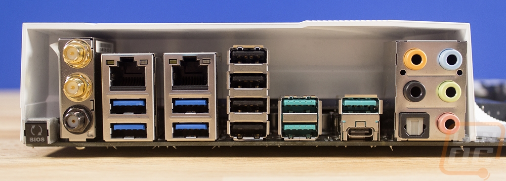
For the rear I/O Asus didn’t do too bad with connections. They used the extra space from not having to worry about onboard display connections to double up on network connections. Both are Intel NICs but one is the I219V and the other is the I211-AT. Both have LAN Guard support so you have some protection for power surges through them. Then there are the three wireless antenna connections. The two gold connections are for the Wireless AC that is also running on an Intel NIC. The bottom darker port is for the new Wireless A. It has its own antenna and it doesn’t have backward compatibility like AC but the speeds are crazy 4.6 Gbps over AC’s 1.3 Gbps. Of course, those are in lab numbers. On the far left is a BIOS reset button. Then on the far right is the standard 5+Optical audio layout. For USB you get four USB 3.1 Gen 1 connections in the dark blue and four USB 2.0 with the black. The greenish connections are also USB 3.1 but they are Gen 2 that have additional bandwidth and the small Type-C connection is also USB 3.1 Gen 2.
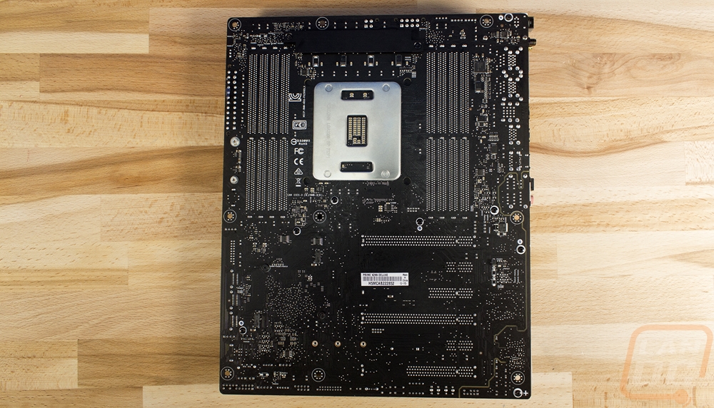
Taking a look at the back of the board, there isn’t anything too crazy going on like M.2s on ITX boards. The back gives us a better look at the black PCB. You can also see the split audio circuitry that goes all the way up to the rear I/O. Beyond that the back f the PC has the certifications and overall you can see just how packed full the board Is with just about every area in use.