Building the Infinity
As I already mentioned, the Infinity keyboard is a DIY project meaning you do have to build it so before you get going you need to have the tools to get everything together. Here is a list of what I had ready to go for the build.
Kester 44 Rosin Core Solder 60/40 .031
A work area
Time
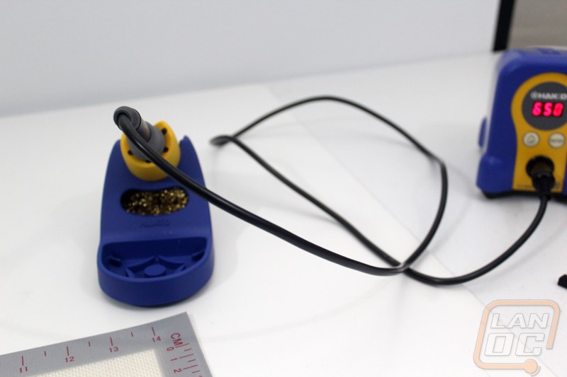
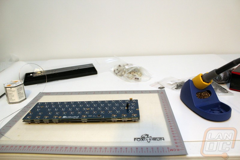
With our table setup I warmed up the soldering iron. With the solder I use I typically run the iron at around 450 to 550, ideally you want it to be hot enough to melt the solder completely but not too hot because you can damage the PCB. While letting that warm up I went through and took a quick inventory of everything to make sure we had it all.
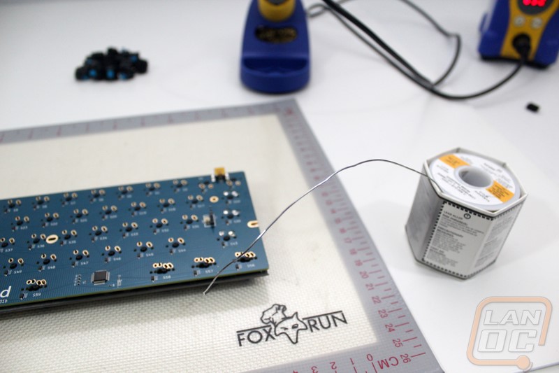
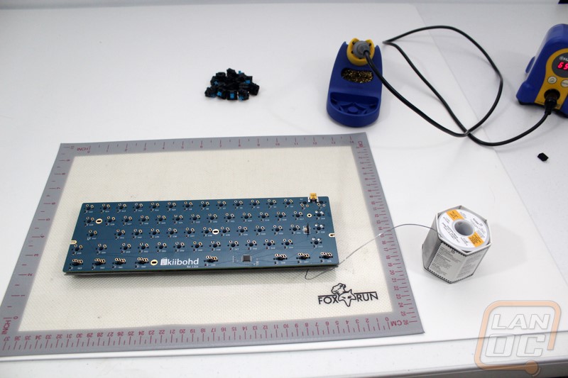
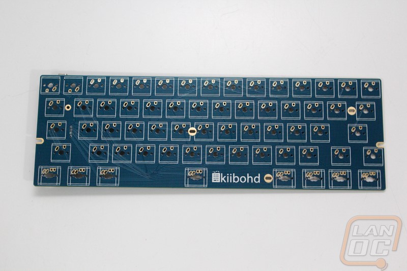
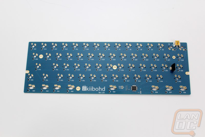
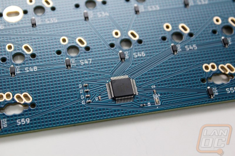
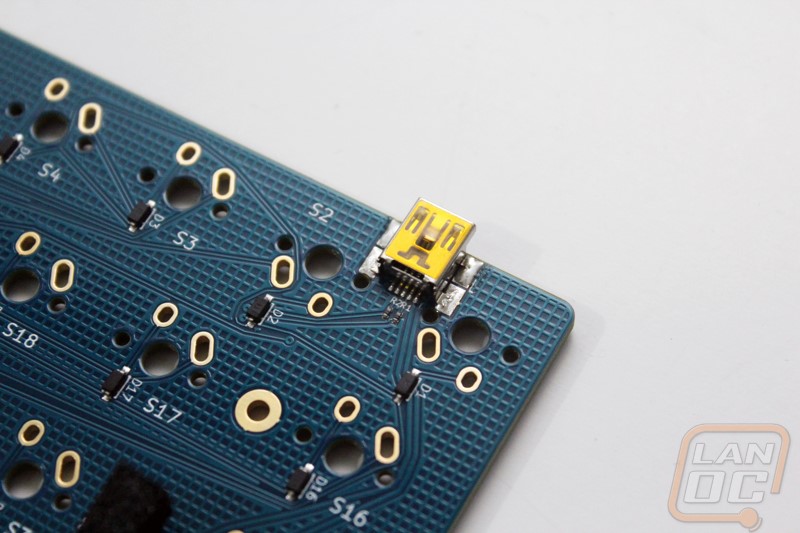
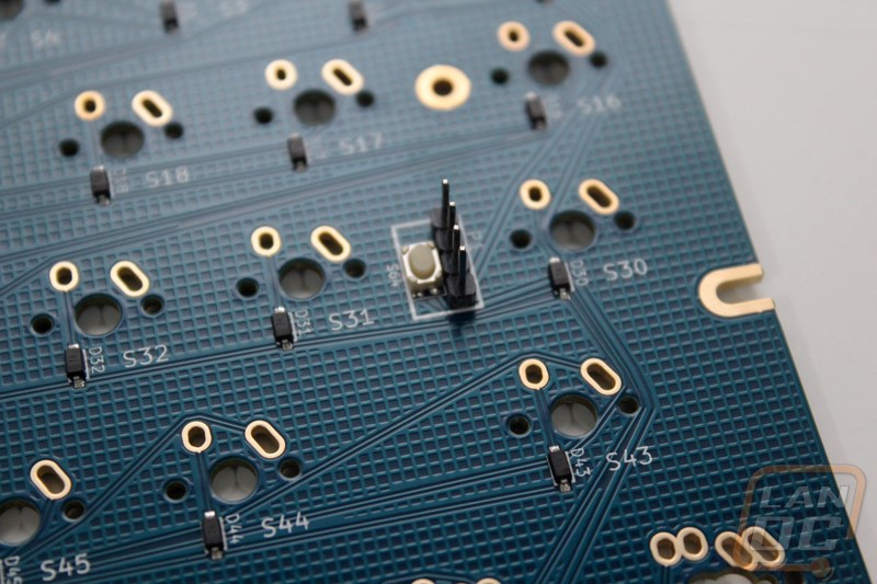
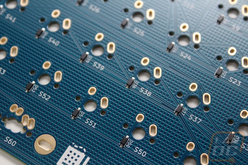
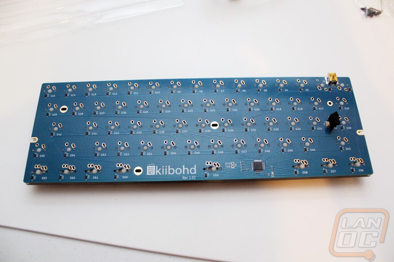
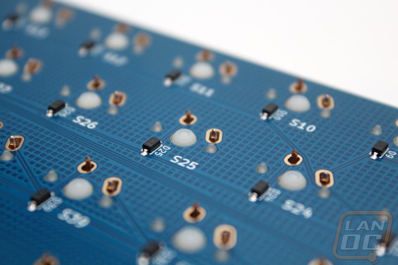
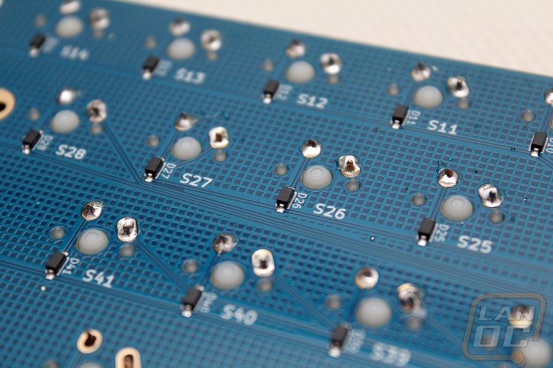
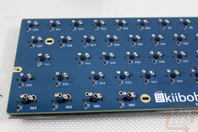
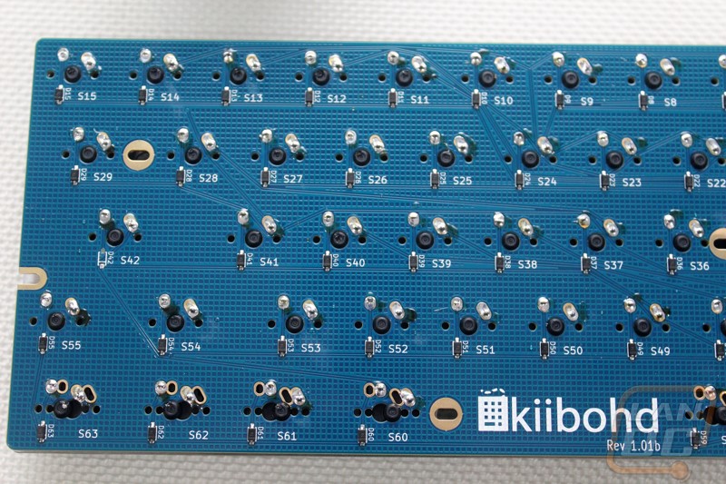
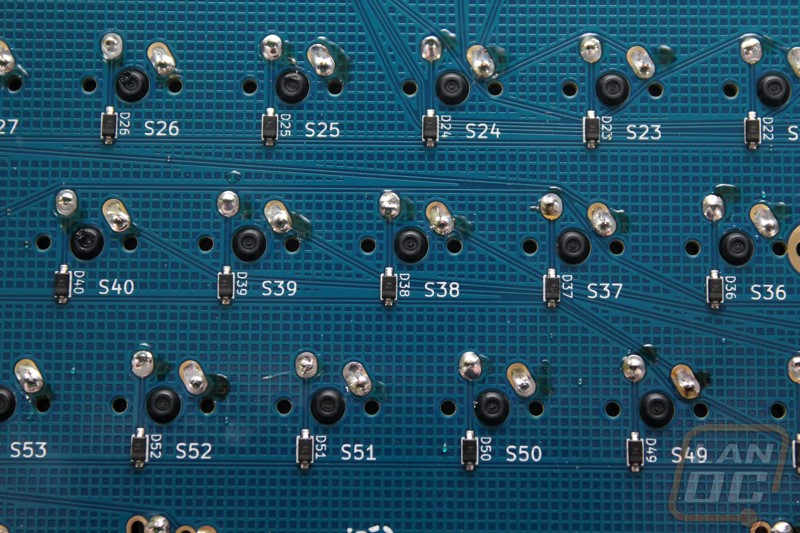
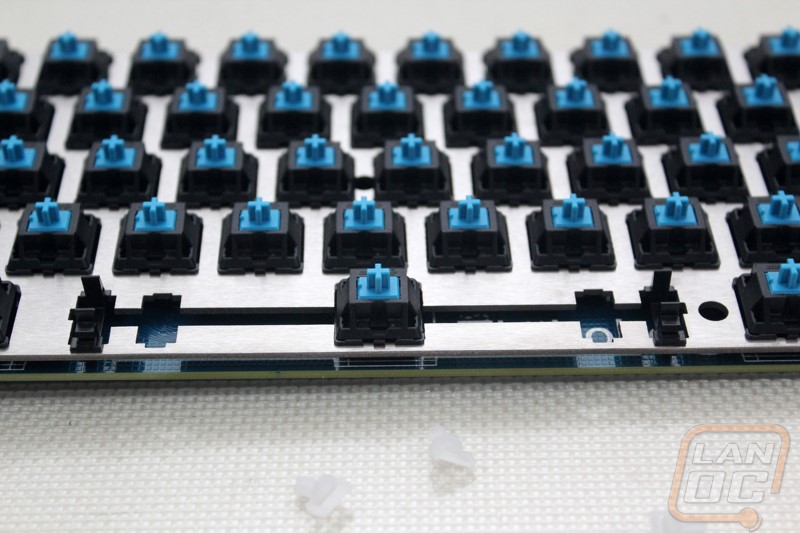
The biggest component is the 60% sized PCB. Massdrop has made this MUCH easier than working with the ErgoDox because the PCB actually comes with the diodes pre-soldered and the controller is built into the PCB as well. Not having to deal with the surface mounted diodes is a huge relief, they are what took up the most time and frustration when building the ErgoDox. To keep things simple the PCB does have a few things printed on it. On the keyswitch side each switch mount has a box around it. Down on the bottom row where they had to design support for the US and Japanese (hacker) layouts the switch locations have two boxes. If we take a closer look at those specifically we can see that in order to be able to fit the two layouts, each mounting point has two sets of holes for the solder points and two sets of holes for the PCB mounted switch mounts.
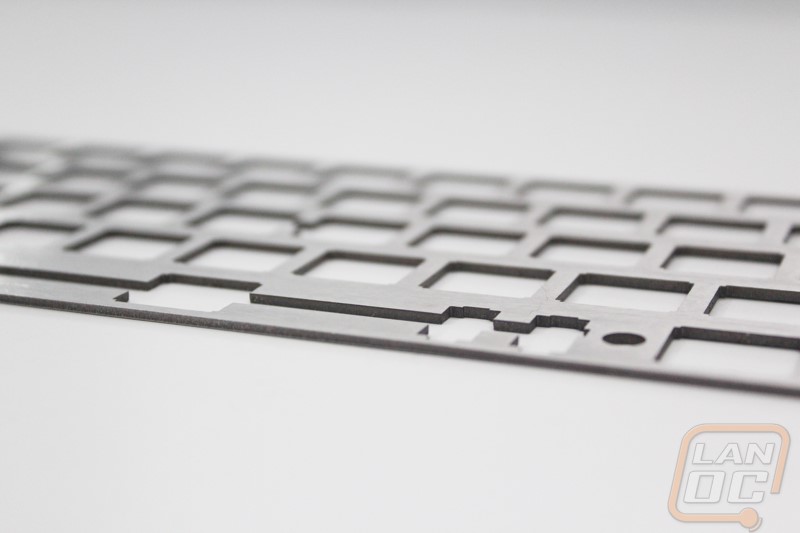
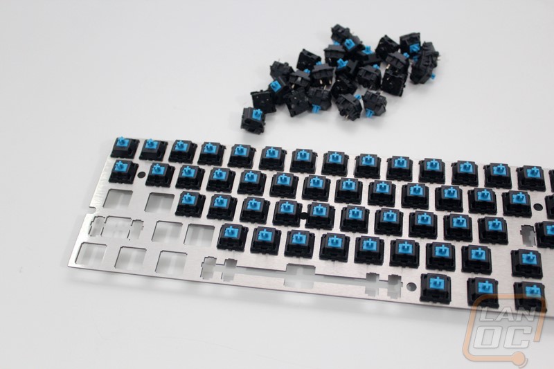
The backplate is made of stainless steel and has cutouts designed specifically to support both a standard Cherry MX style keyswitch as well as a Mitias keyswitch. In addition the cutout allows for you to be able to take the Cherry MX style keyswitch apart without having to desolder and remove it, something you normally can’t do on a plate mounted keyboard. There are five holes in the plate that give access to the five mounting holes built into the PCB, these mounting holes support standard 60% keyboard cases. Then of course it has the cutouts for the stabilizers as well. On the bottom row we do have mounting options for both a longer and a shorter stabilizer.

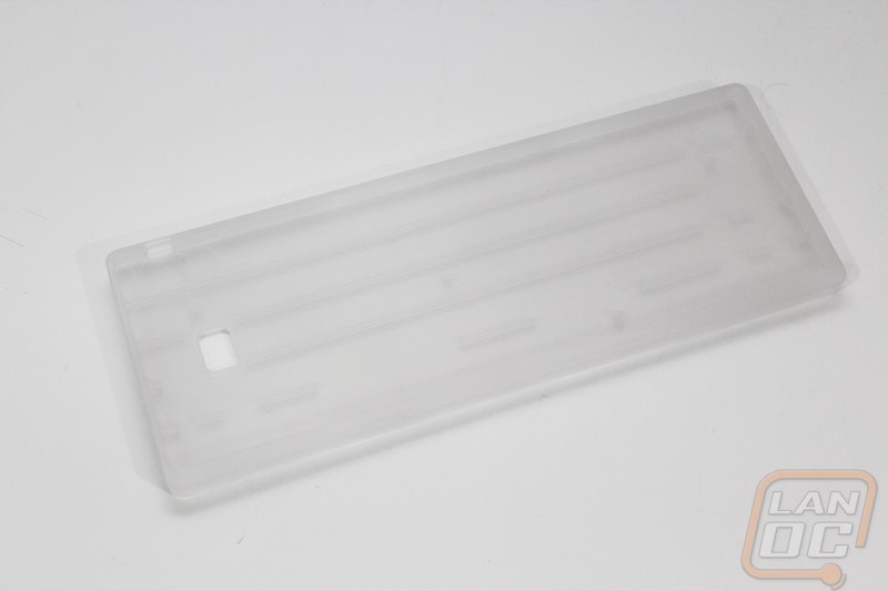
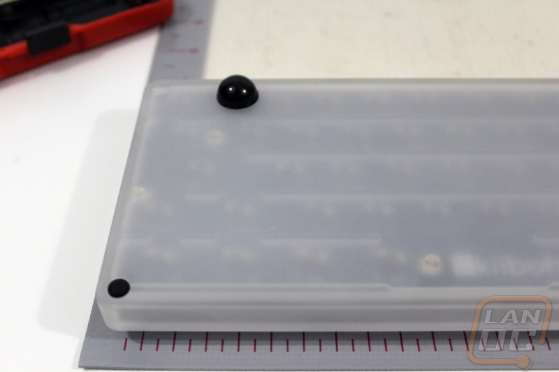
For a case Massdrop sent a Tex Acrylic 60% case with a fat front lip for our original kit. The Acrylic case is designed flat where most cases have the angle built into them and the case itself is a transparent acrylic with a frost to give it a little style. For the second build they actually sent an even nicer Vortex black aluminum case, because of this I actually painted the back plate to match.
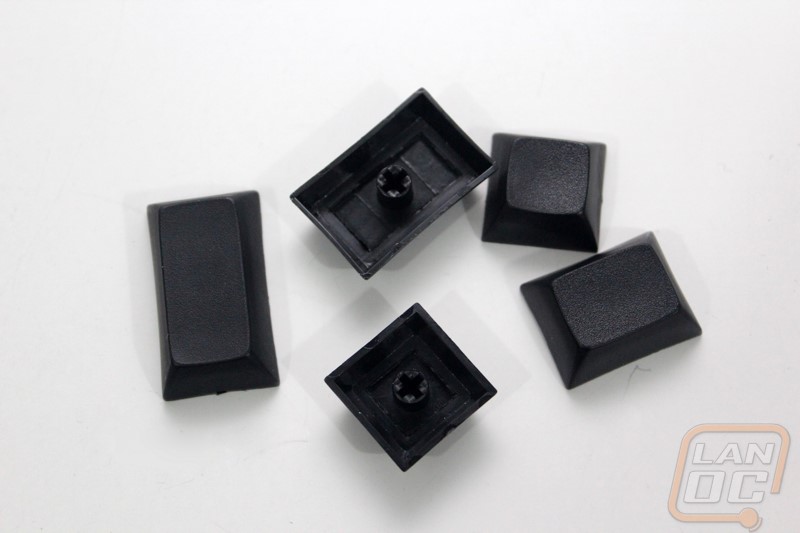
For keycaps we have a set of Signature Plastic’s black PBT DSA keycaps.
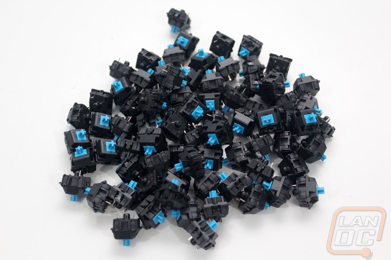
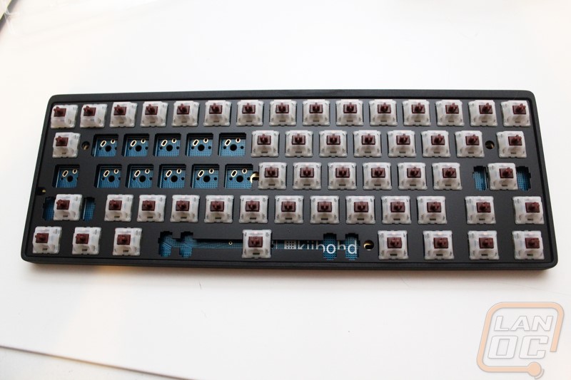
Our original build was built with Cherry MX Blues and on the second build they sent Cherry MX Browns. Oddly enough right before starting that build a set of Gateron Browns (that are also available with the Infinity) came in that I ordered from Massdrop so for the second build I gave them a try.
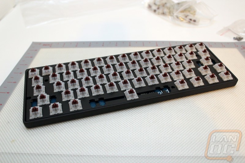
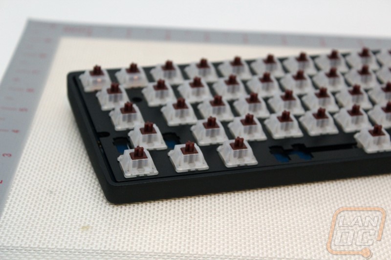
After taking an inventory, I jumped into the build. I actually went about this in two different ways after learning a little on the first build. The first time around I put all of our keyswitches into the backplate and then from there lined up and attached the PCB. I would recommend actually only putting in switches in each corner and lining up the PCB because the more switches you have installed the harder everything is to line up. When installing each switch make sure to check the two pins on the back of the switch before installing it to make sure they aren’t bent as well. You also want to make sure you are completely pushing the switches in place. For the second build after installing the four in the corners I put the plate and PCB into the case while putting the other switches in. Doing this lets you have a little leverage while completely supporting the PCB. If not you will most likely bend the four pin connection on the back of the PCB.
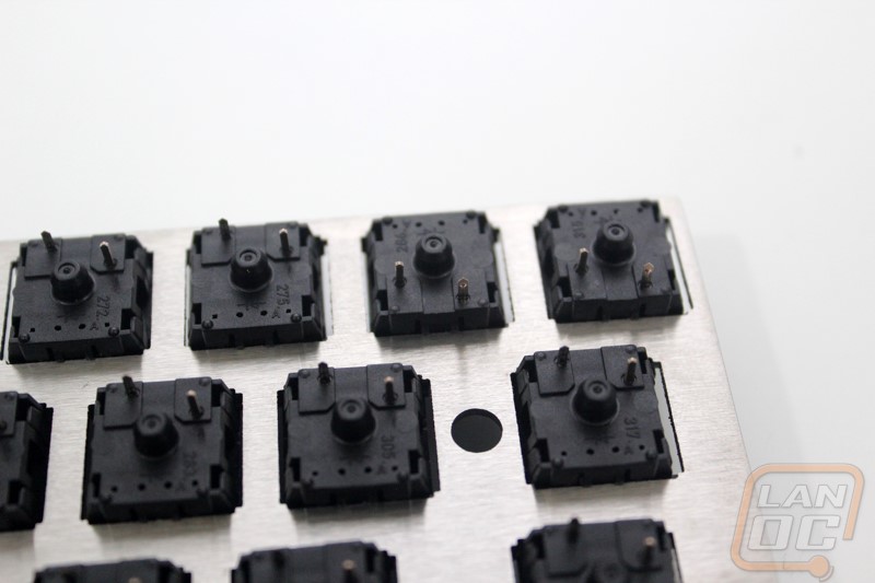
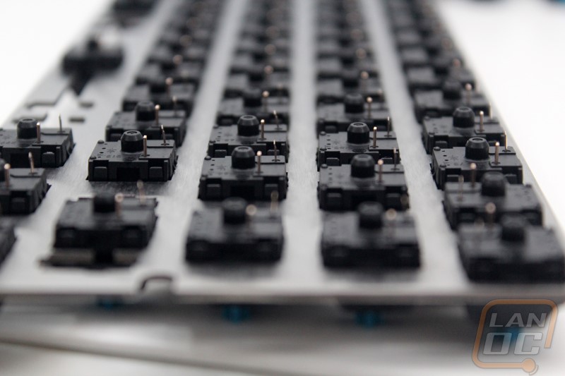
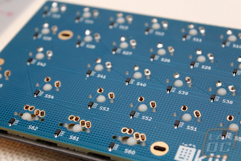
Once I had all of the switches pushed into the backplate and PCB I flipped it over and visually double checked that each switches pin was through the PCB. It is each for a slightly bent pin to get caught and bent over behind the PCB, it is much easier to fix this now than to do it after you solder.
Now we are good to solder. If you don’t have any experience soldering I would highly suggest that you practice. This is an easy task but I’m sure you would rather make mistakes on something smaller than your new keyboard right? Basically you are soldering two pins for each switch for a total of 126 pins. Take your time and when you are done go back through and visually check each solder joint to make sure it looks good.
With everything soldered I moved on to installing the stabilizers. First we have to install the clips into the mount holes, when doing this on the spacebar grab the stabilizer bar to make sure you are installing the clips into the correct holes as well. The clips install with the plain side facing the top of the keyboard and the side with the mounts for the stabilizer bar on the bottom. On our first build the clips installed perfectly but on the second build they must have changed the hole size slightly because the hole pushed on the clips. To fix that I actually had to file the clips down slightly to keep everything from binding up, hopefully they have that fixed for the third drop. With the clips installed you just have to snap the bar into place. Next you need to install the small adapters into the back of your keycaps, when you do this make sure the longer side is pointed to the top of the keyboard. When installing the keycaps later you will need to hook the stabilizer bar into those for it all to work.
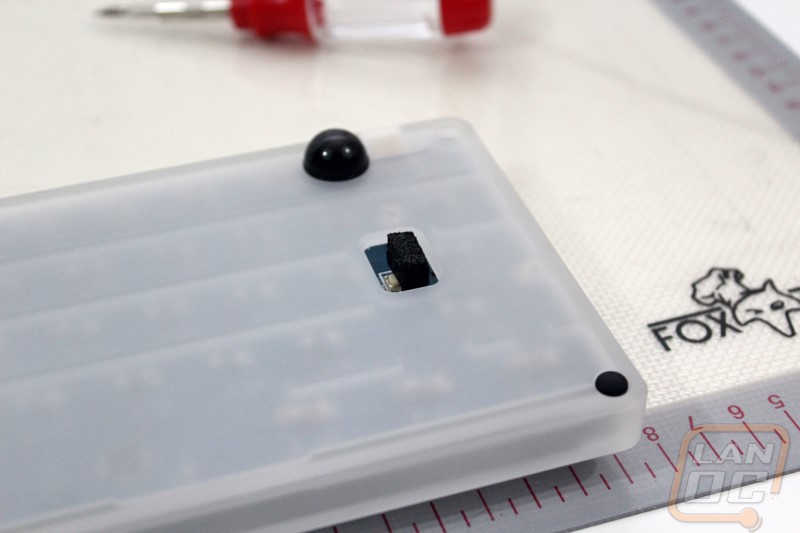
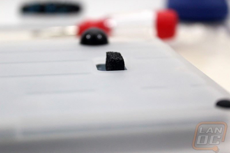
With the Tex Acrylic case after installing the PCB/backplate into the case with the five screws we did also have to bust out the included feet and stick them onto the designated locations. I might have gone with the smaller mounts on both the front and back but the four pin header that sticks out the bottom of the PCB actually sticks well out of the this case so I went with the tall feet for the rear to angle everything up. The Vortex case that they sent over for the second build didn’t have this issue because it was designed with an angle in mind from the start. The new injection molded cases that Massdrop is going with for the 3rd drop also look to have that same angle.
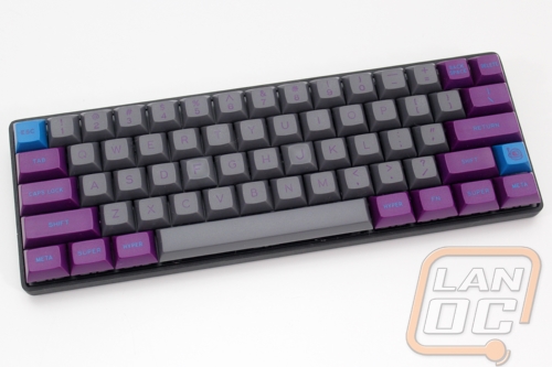
Here’s a shot of our second Infinity with everything together as well as the black backplate and black Vortex aluminum case.