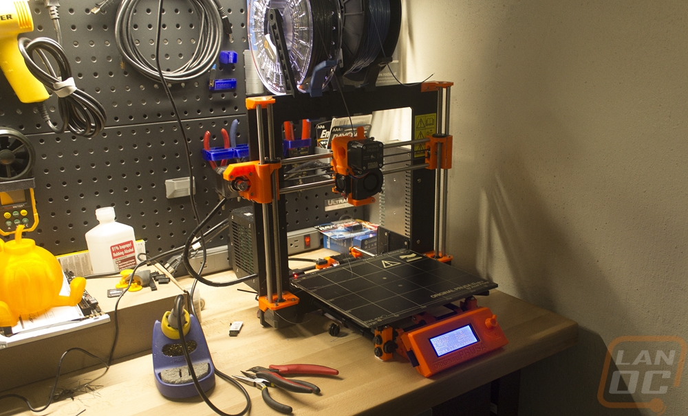
A few years ago when I first replaced my desk I wanted to add a clock to the office to keep track of time better. I didn’t want something normal and went with a retro looking flip clock. The flip design was something I always liked but the model that I picked up didn’t fit well under my monitors and later the noise from the motor, not the actual flip started to drive me crazy. After that, I kept looking for something to replace it with but never found what I was looking for. Then about 6 months ago I came across Nixie tube clocks and fell in love. The prices though were just too much. I decided to build my own using a kit I found online and printing the outside components. The hardware came in during the Intel launch and this past weekend I set aside the time to start working it.
Title: Building and 3d printing a Nixie FunKlock
Hardware provided by: Myself
Written by: Wes
Pictures by: Wes
Amazon Affiliate Link: HERE
Nixie clocks are available in a range of different designs, even in the kit form but I was looking for something small that would fit under my monitors. I found designs on eBay and Amazon that looked amazing but when it came to the price they were WAY out of my budget. The kits on eBay were a much better price but they weren’t as compact as I would like. That is when I ended up on PV Electronics, a UK-based retailer who almost completely focuses on Nixie Tube Clocks. They have large kits and small kits but their FunKlock Kit was small enough for what I needed and the prices weren’t much more than eBay. A kit with tubes was a $64 plus shipping costs but I still needed a power supply and a case. They sell both as well and the finned case they have is amazing looking but I decided to go a different route. In my searches to see if I could get their clock from someone in the States I came across a Thingiverse design that was recently uploaded of a FunKlock case. The design was more compact than the PV Electronics designs and it was going to cost me a lot less.
Before ordering the FunKlock kit I did my research. I studied the build guide to make sure it was something I would be capable of doing. I also looked into the power supply requirements and decided that one from Amazon would be cheaper for me to get. You need a 300 mA or higher rated 12v adapter with a 2.1mm plug with center positive. I picked up a cheap 500 mA model on Amazon with free prime shipping and good reviews but you might also have one just floating around the house.
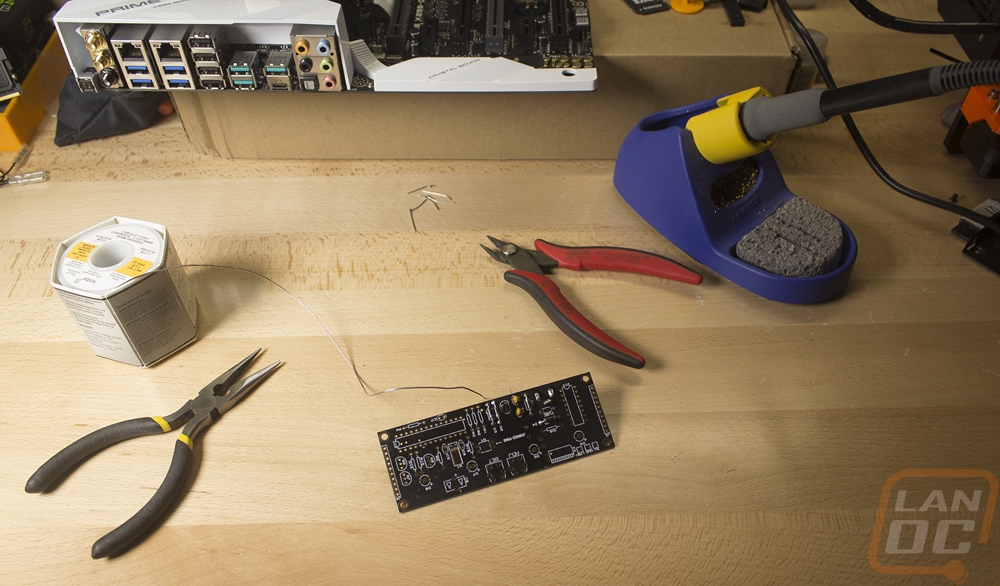
Tools Needed
For tools, they recommend a soldering iron, solder, wire cutters, wire strippers, a multimeter, and you might need a small flat screwdriver. You don’t need the screwdriver though and the wire strippers can be scissors or in my case, I just used my wire cutters on both. Beyond that, I would recommend a small pair of pliers and if you are going to print a case you will need a 3D Printer and Filament.
Here is a list of what I used for the build
Hakko Digital FX888D Bundle (this had my wire cutters with it as well)
Kester Solder 60/40 Stand, 0.031" Diameter
Original Prusa i3 mk2 (for filament I used the Prusa PLA Extrafill Vertigo Grey that came with the printer)
You will also need a workspace that you can solder on or a silicon baking mat to make sure you don’t damage anything.
Putting everything together
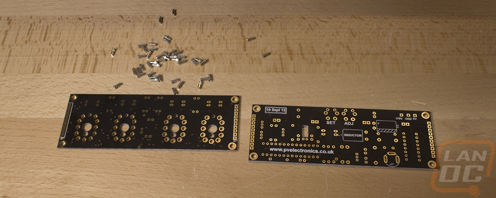
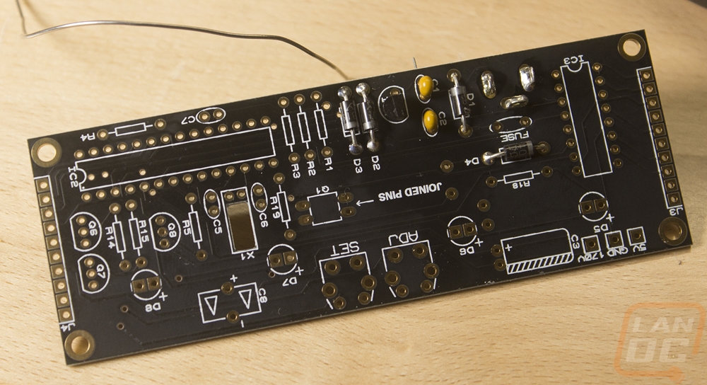
So when the clock kit comes in you actually get a small box. Inside is the two PCBs joined together, a bubbled wrapped tube with the four nixie tubes inside, and a static protective bag sealed with a whole list of components. I sorted out all of the components by type and then I got started on the first step, installing all of the tiny sockets that the nixie tubes plug into. Soldering them was easy but just getting them all put in and moved from my desk to my workbench was another challenge altogether. I knocked part of them out twice and twice I spilled them all when trying to flip things over. A small piece of solid plastic or metal would be much easier but I used the second PCB and got the job done.
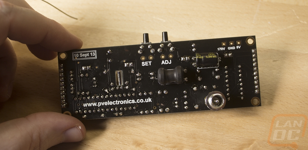
With the sockets soldered in place, I then started working my way through the included instructions. Speaking of, this is not a complete guide of how to build the electronics, PV Electronics did a great job of that with their instructions go use those. Here is a link to the current version, but they can change so be sure you have the one that matches the serial number of your kit. Anyhow the first bit was extremely simple. It covered the low voltage circuit, you get that together and then they give you instructions on how to hook it up to power and test it.
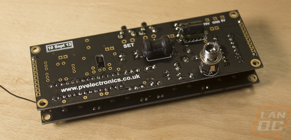
From there you get into the high voltage stuff including a socket to install the 8-bit controller. There is another test only this time you are checking the 170-volt circuit so be extra careful with this one. The instructions slowly guide you through everything else including joining the two PCBs together with detachable risers. The only thing that is difficult here is figuring out which resistor you need and you can use your multimeter to do that. I used the small pliers that I suggested to bend the wires with nice 90 degree bends or if you have a bender or you can print one.
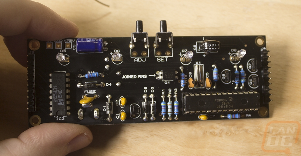
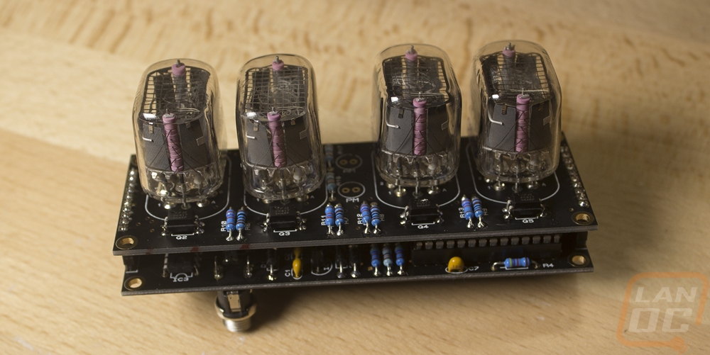
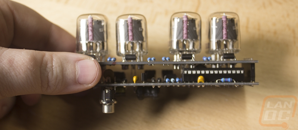
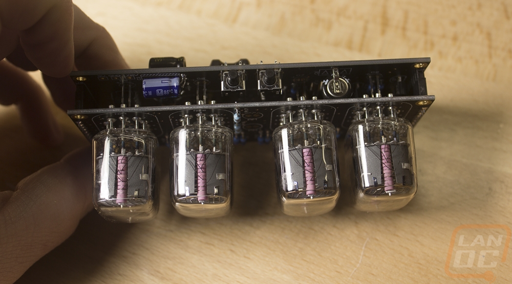
Once altogether the last thing you have to do is install those fancy nixie tubes into the sockets. When I took this picture I didn’t have them completely installed but they will still stick out. If you have a case already you can also install the two neons that sit in between the middle tubes. For me, though I had to wait to get my case all printed. I would also suggest going back over all of your solder connections to make sure nothing is touching. On the risers, I use my multimeter to make sure none of the pins were soldered together. Then I went back and added solder to the opposite side of the PCB on things like the resisters that have room to get to both sides.
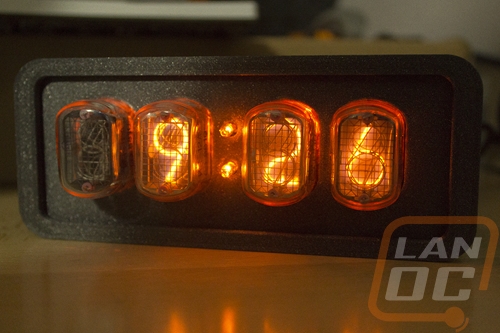
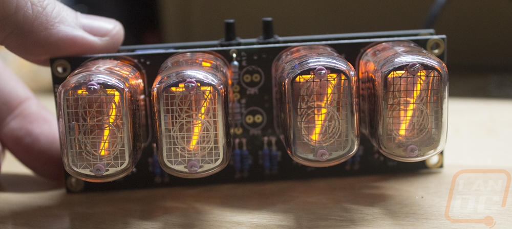
I powered everything up and it the default mode to test everything flips through 0-9 to make sure each layer works. You then use the top buttons to program the time. I also took the time to go into the program mode and flip through the list of options the clock has on page 18. Seriously they did a great job on the firmware here, you have a lot of good options.
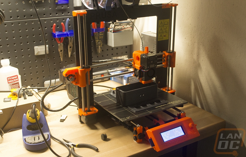
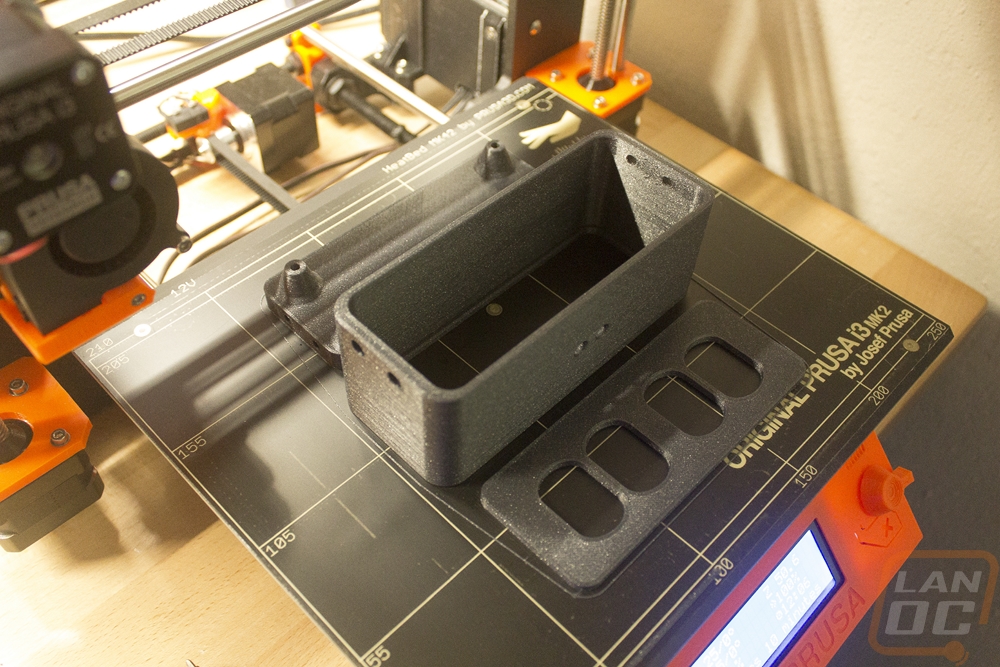
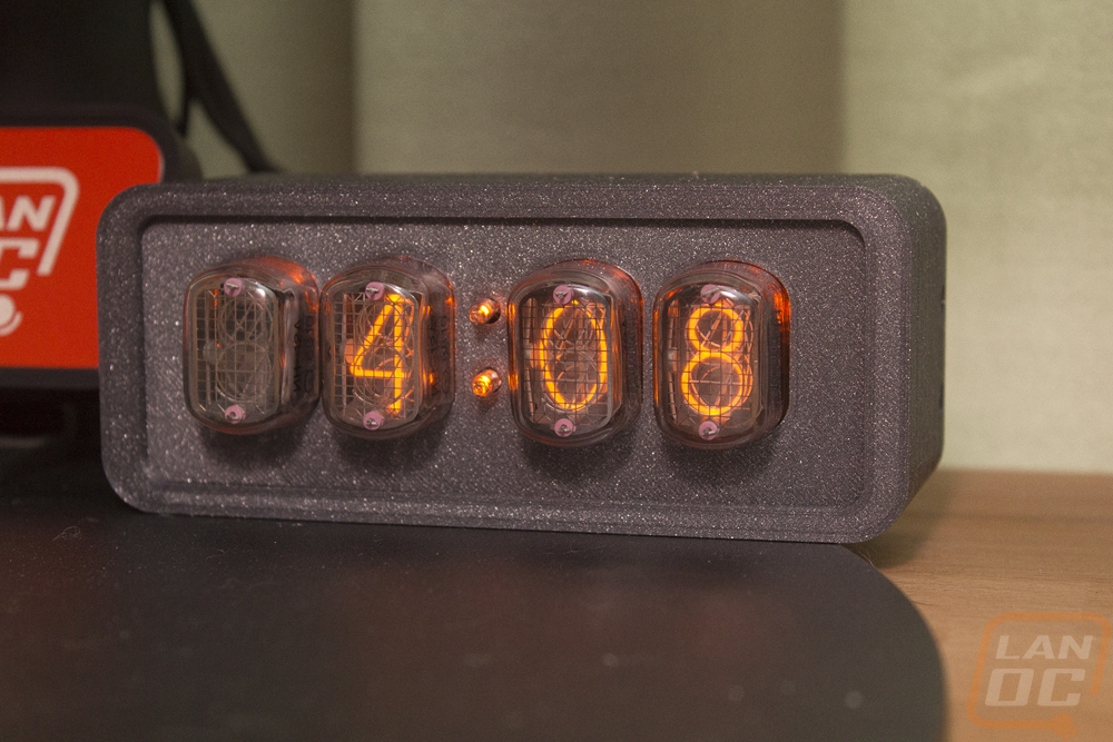
With the clock working I downloaded that case design and set it up to print overnight on the Prusa that I’m testing. There are three components, the main housing, a front plate, and a back panel. I went with the dark gray with sparkle filament that the Prusa came with because it looks amazing. The three pieces ended up taking 11 hours to print. If you have a carver or a laser cutter you can also cut out a custom front panel, something I would love to do in the future to swap this to a smoked acrylic or even wood.
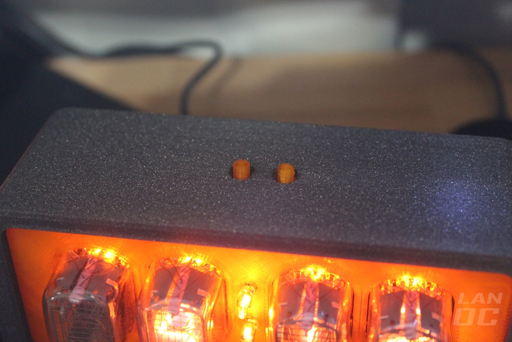
With the case printed I could finally install the neons, you have to know the overall length they need to be to not stick out too far of the case. It took me a few tries. They include tubing to make sure the leads don’t touch and once you have everything to the height that you prefer you can heat those up if you want to get them tight.
The case I printed did take one small modification on my part. The power plug on the back was lined up perfectly but the plug from the power adapter I picked up was a little thicker than the hole. I used a stepper drill bit to make room for the plug without completely opening up the hole. Last but not least if you print your case you will need to pick up a few fasteners to hold everything together. The design could really be changed slightly to only need those M3 bolts as they can screw into PLA really well but everything can be picked up at most hardware stores or in my case a Fastenal.
4x M3x5 5mm OD brass inserts
4x M3x15mm hex bolts
4x M3x30mm hex bolts
4x M3 nuts
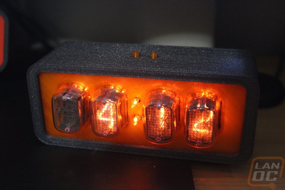
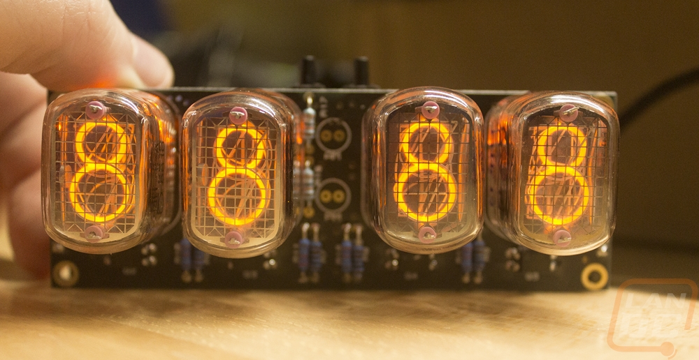
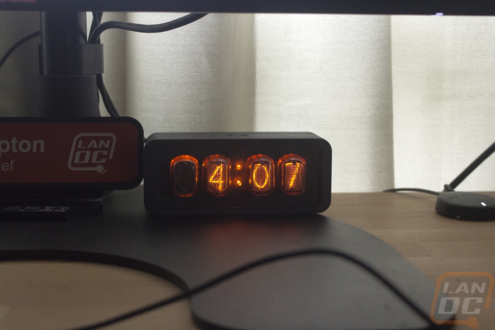
The end result is amazing if you ask me. The tubes are really unique and easy to read and you can pick your own backlighting. The firmware even lets you set the brightness settings if you want brighter or nothing at all. The case designers clock looks much better with its wood and white design but I think later if I swap the front panel to a smoked finish it will really improve the look of this one and I may consider sanding and painting the case. Overall the clock cost considerably less than what any of the complete Nixie Clocks costs and honestly it is always exciting to build something and to be able to show off what you made. Here is a price breakdown.
$69.30 Clock components
$5.99 Power Supply
$4.20 You use about .3lb or 136g of filament
$3-5 Screws
Total Cost – $84.49
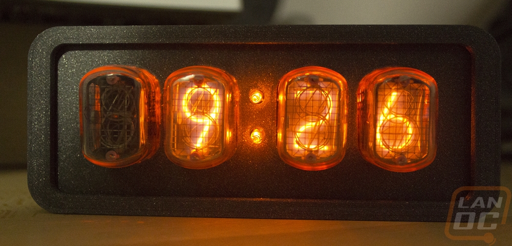
The kit wasn’t perfect, two of my four nixie tubes were much lighter than the other two. I like it enough that I really want to do another in the future, PV has a few different designs that are really cool looking to vertical tubes, RGB lighting, temperature readouts, and other features. Looking through their designs they have a few other kits that have a lot of the components pre-installed as well if you are afraid of messing something up when building one. At just under $85 my build was still a lot less than any of the designs sold. Going with a pre-made case would add another $15-$45 in costs but even that still is better.
Even after finishing up my clock I have been toying around with it. I designed buttons that are compatible with the case for the top two buttons and I toyed around with transparent orange for the front panel. The cool thing about the case design is I can print or cut our many different colors or materials and change the look of the clock up altogether. Will the orange stay? Most likely not, but the transparency is cool.