Board Layout and Pictures
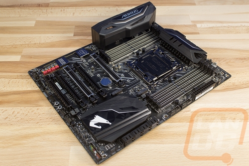
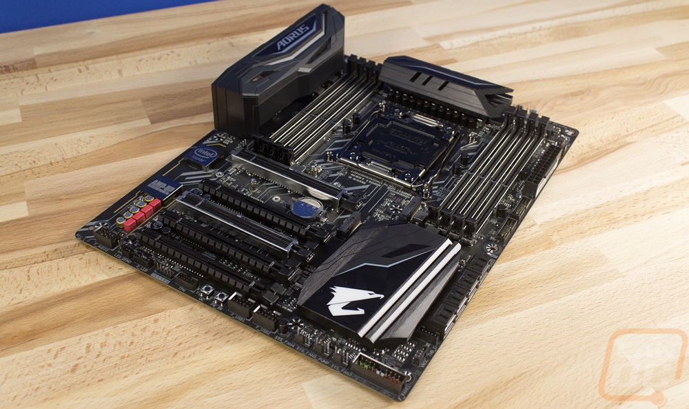
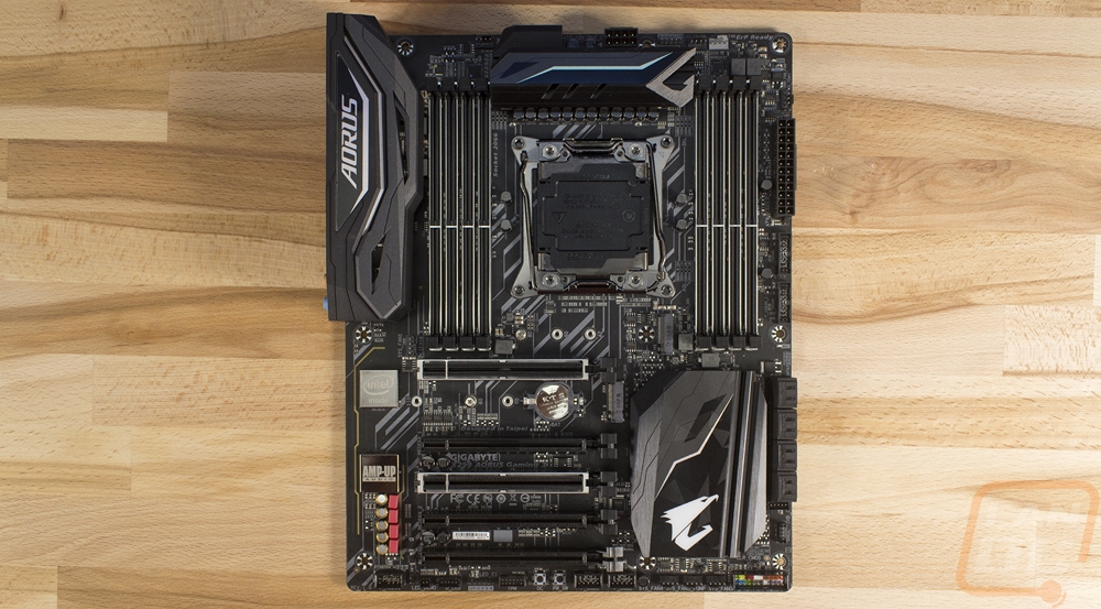
With this generation, Gigabyte has gone to great lengths to push a very color neutral theme on their boards with the AB350N being the exception. The X299 Gaming 3 might be the lowest end of the three current Aorus X299 boards but they didn’t slip in any special colors or white shrouds on an otherwise black board like in the past. This is a big deal, for our Crush build I went way out of the way to pull our Gigabyte board apart to paint all of the white black to match everything, this time around that doesn’t have to happen. Of course, that’s not to say there isn’t any style, they did make the board look good. They have an angular design on the heatsinks and the rear I/O cover that is a little like the Asus Strix styling, a black PCB with a gray design on it, and then things like their RGB lighting around the PCIe slots and on the chipset heatsink.
Below is the rear I/O shield, it has an angular design with a touch of silver and the Aorus branding across the top. It has a few small holes that match with the styling as well but the main reason for this is to cover up the bright metal finish on the rear I/O to keep the whole board blacked out.
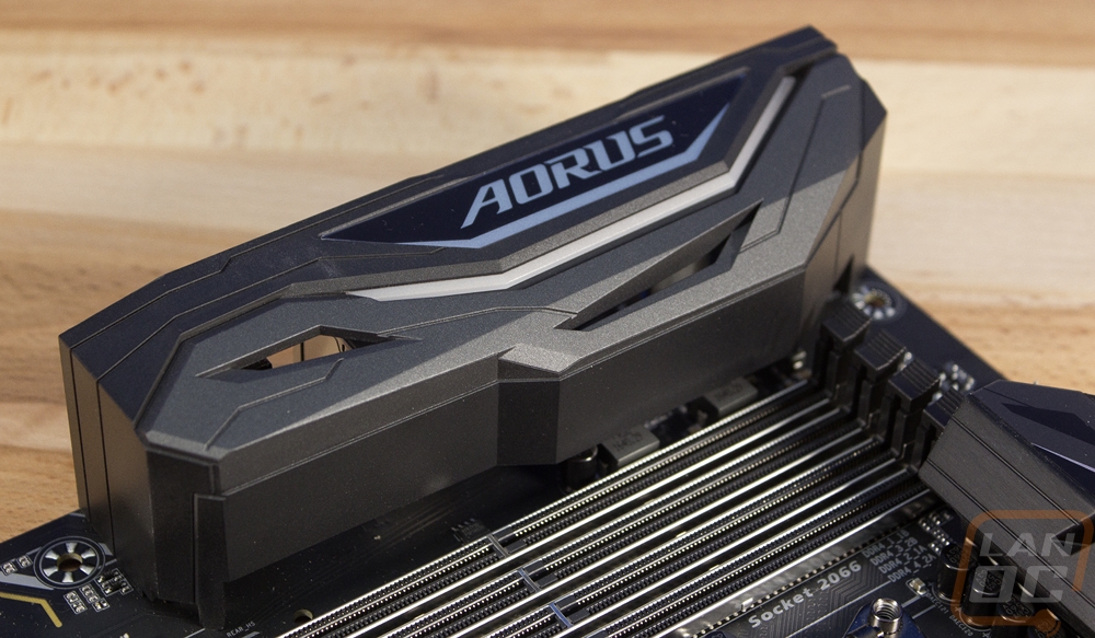
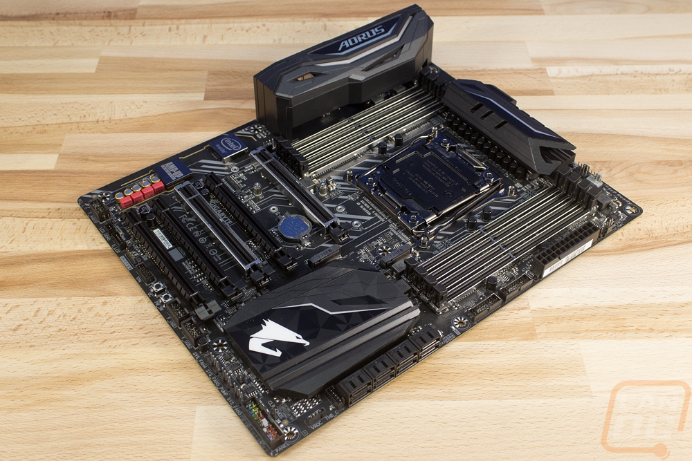
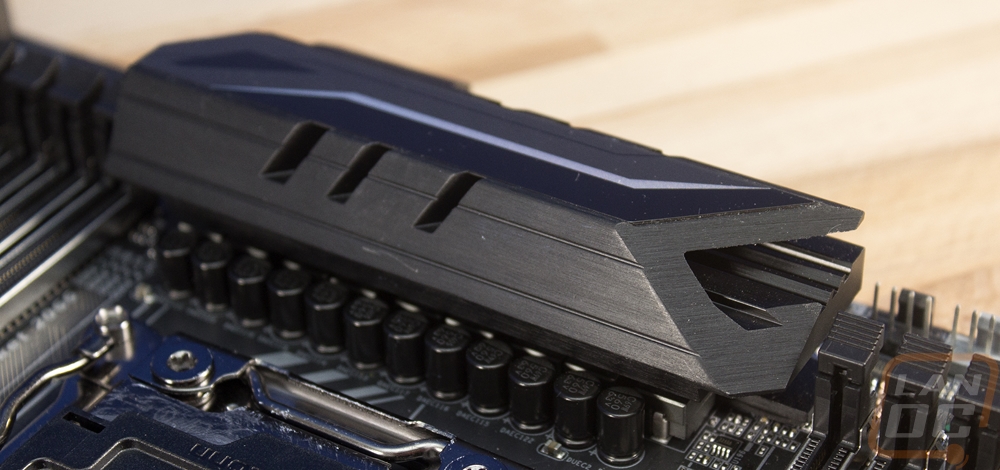
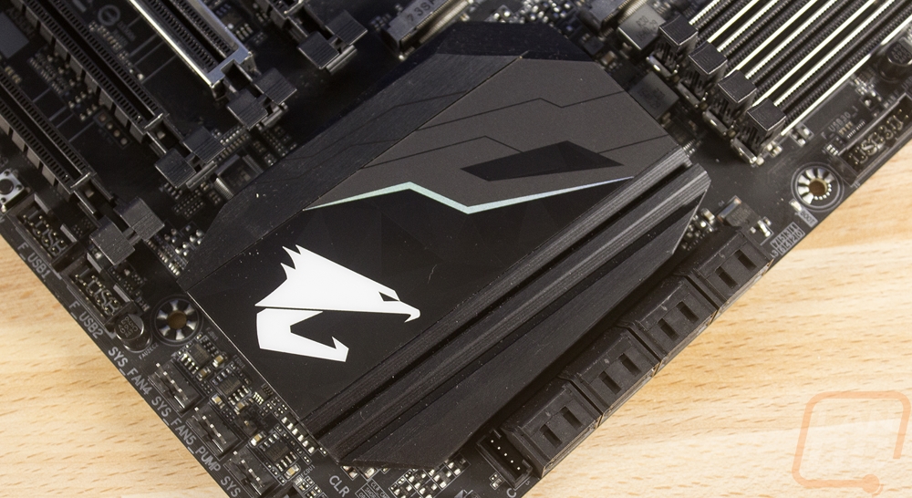
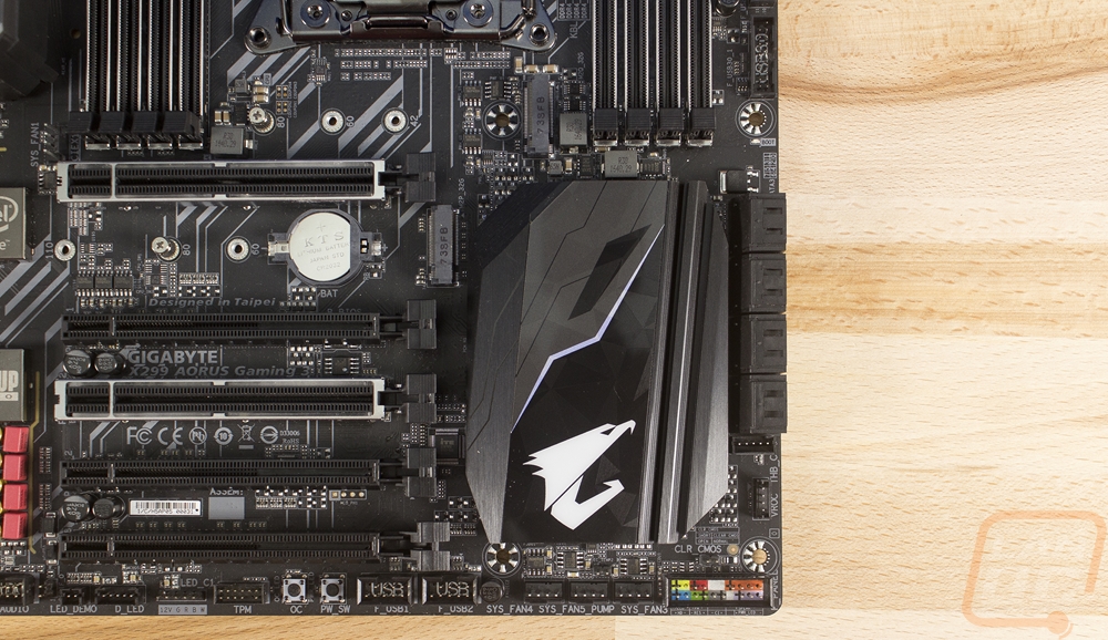
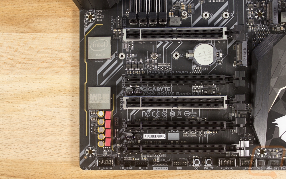
For cooling, there are two heatsinks. There Is one across the top of the CPU socket that cools the power circuitry. It isn’t too large but it is large enough to keep things cool. The aluminum is anodized black and on top, they did add a black panel with a silver accent. The chipset cooler is in the bottom right corner of the board and it is much larger but very low profile to fit under long PCIe devices. It is also anodized black and on top, it also has a stick on panel. This one has a large Aorus logo that lights up in RGB and a lightning bolt looking accent across the middle.
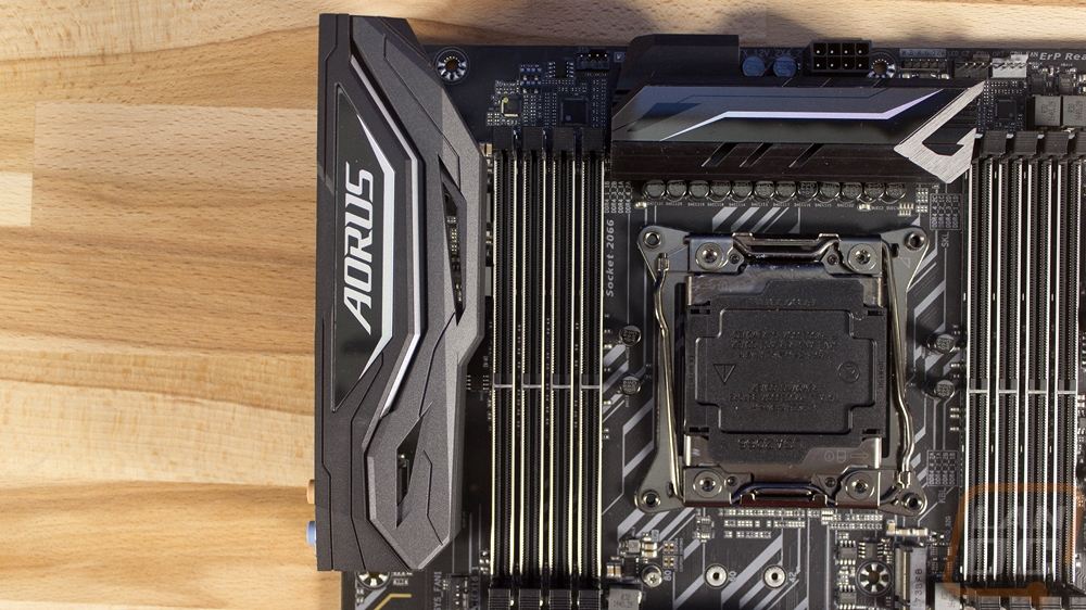
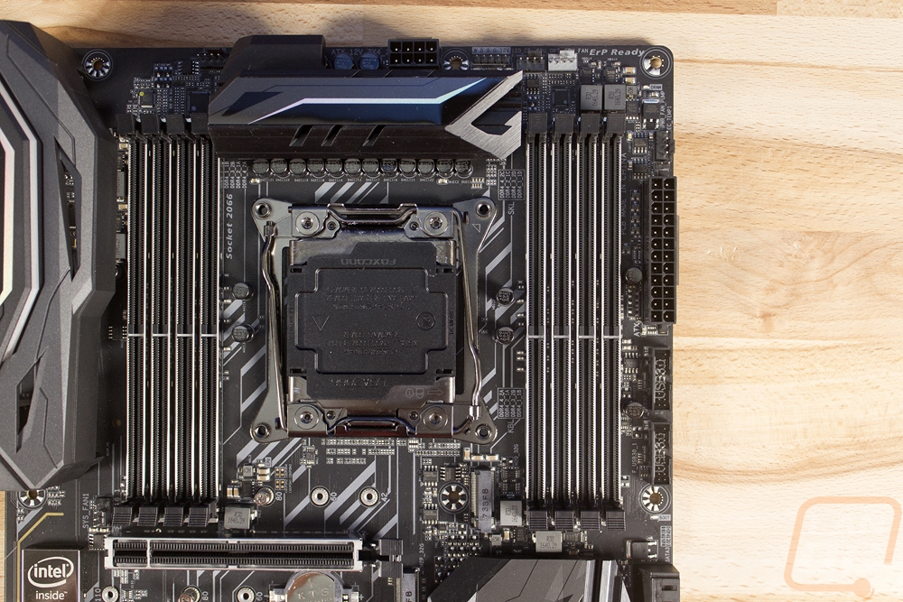
Okay starting up in the top left corner lets check out what the Gaming 3 has going for connections and other interesting features. The rear I/O has that nice looking cover over it and that bumps right up against one of the two sets of 4 DDR4 DIMMs that are on both sides of the CPU socket. There is a system fan header just under the I/O and next to the ram as well as another up above that left set of ram. Then above the CPU, there is a single 8-pin CPU power connection. Moving over for there you have two more 4-pin fan headers for the CPU and optional CPU fan and with them, there is a wRGB digital lighting connection. That one does full RGB along with pure white lighting with support for individually controlled LEDs with compatible strips. Also in this view, there is actually a shorter M.2 slot tucked up under the CPU socket between the ram.
On the top right there isn’t too much going on, plus I touched on some of it in the previous section. Along the right edge, there are a few things though. There is a 4-pin fan header, our fifth so far. Then below it is the normal 24-pin motherboard power. Then there are two USB 3.0 headers for those cases with support for 4 USB 3.0 headers.
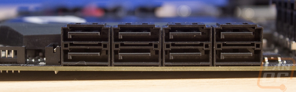
For the bottom right the the chipset heatsink takes up most of the space but Gigabyte did manage to slip in a few things. There are eight right angled SATA connections right up against the chipset heatsink. The front panel connections are all in the bottom right corner with each connection labeled with a bright color and plus signs to show any polarity when needed. The clear CMOS jumper is also right above the front panel connections and should still be accessible, even with a video card installed in the PCIe slots. There are three more 4-pin fan headers, two for system fans and one for a watercooling pump putting us up to a total of 8. Then there are two USB 2.0 headers for cases that don’t have USB 3.0 or for some of the newer devices like fan controllers and lighting that require a USB connection.
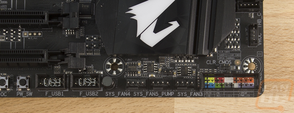
Moving over along the bottom edge the Gaming 3 has a small power button with an OC button right next to it. Then there is the TPM (trusted platform module) header. There is another wRGB digital header down here as well so you can hook up lighting from the bottom and the top. The front panel audio header is over on the left and it is hooked to the Realtek ALC1220 powered onboard audio. The LED Demo header is an interesting one that is actually only there for Gigabyte to be able to show off the board at events. When you apply power to this one you don’t have to have a CPU, RAM, or even a power supply hooked to the board to still see the built-in LEDs in demo mode.
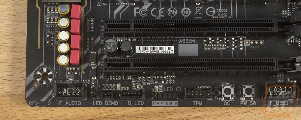
In with the PCIe slots, they did slip in a second M.2 slot. I like having two M.2’s but the placement of this one isn’t what I would like to see. That top slot is almost always taken up by your video card and right now video cards are 2-3 slots wide. This means the M.2 is guaranteed to cover up the slot and put, even more, heat into an M.2 drive that may not run cool in the first place. For slots, all of the slots are full x16 length slots. Two have metal shields and built in RGB lighting. All of the PCIe slots have levels on the left side to help make it easier to figure out. The second and fourth down slots are x4 speed. The bottom slot runs at x8 and the two slots with metal shields are both x16 slots. Now, this gets complicated when we get into the 28 and 16 lane CPUs of course. Looking through the manual it looks like the 16 lane CPUs leave you with x8 only for the top slot x16 slot and x4 in the second x16 slot. The 28 lane CPU gets x16 for the top slot and x8 for the second x16 slot. Both of these options leave the rest of the PCIe slots shut down, they also only support Crossfire for some reason.
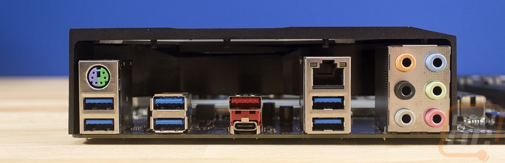
For the rear I/O the X299 Aorus Gaming 3 was well, less than exciting if you ask me. Over on the right, you get a 6 port audio array but there isn’t an optical connection. You then have a PS2 legacy connection over on the left. The network port is connected to the Intel NIC From there the rest are USB connections. Now I like to see a lot of USB but given that there wasn’t Wireless, Dual NICs, or a CMOS reset button they could have filled in that space with additional USB ports but it seems they stuck with what would come on any of those other high-end boards. So you get six blue USB 3.1 ports that are all running on the Intel chipset, then the red port and the Type-C are both USB 3.1 Gen 2. I love that they included the new ultra-fast connections and Type-C, but a stack of four USB 2.0 ports slipped in would have been nice.
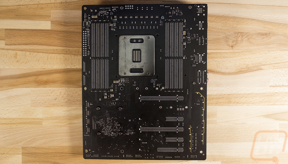
The back of the board shows off that good looking flat black PCB. It also lets us get a better look at the two stripes where the PCB is split to keep interference away from the integrated audio, sadly this view also shows that that separation isn’t as good as it could be, it doesn’t even go around the ports at the rear I/O or down at the bottom near the front panel audio connection.
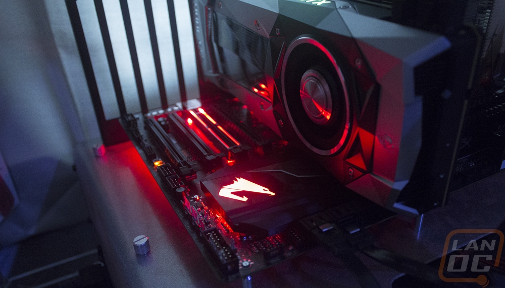
Because I don’t really touch on lighting when I get into performance, here is a look at the lighting on the Gaming 3. The Aorus logo on the chipset heatsink really glows well and the lighting around the main PCIe slots looks good and really lights up our 1080 Ti.