Board Layout and Pictures
So the Z270N Gaming 5 looks a little different than most of the other Z270 boards from Gigabyte this generation. Some of their boards have the white and black theme or the black and red theme but there aren’t too many with their orange theme. Normally this is exclusive to their overclocking focused boards like the SOC boards. As a big fan of orange, I was excited to finally see an orange ITX option but I was surprised they didn’t go with a monochrome look and just use RGB lighting to let people pick their color theme like a lot of the boards are doing now. The orange is mostly limited to the two DDR4 DIMMS and what is visible of the PCI slot but there is a touch on the cooler as well. What stood out to me about this board though was the all metal shroud over the rear I/O. A lot of the premium boards are getting these but you don’t normally see them on an ITX board. They are normally plastic as well, so the all metal design really gives the quality a bump for the Gaming 5. Beyond that, it has a flat black PCB finish but you can barely see that from the top.
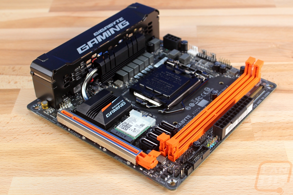
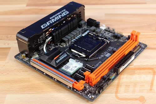
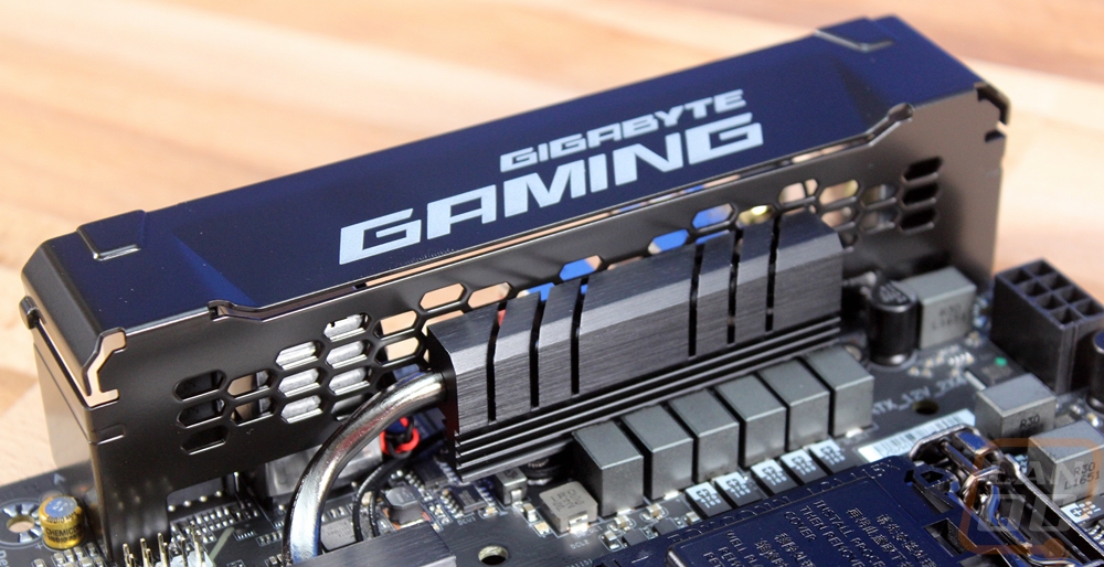
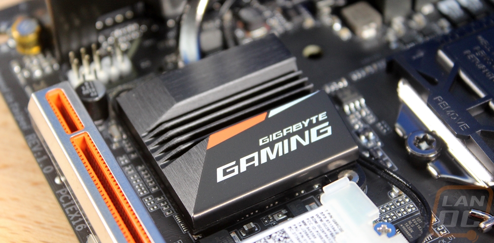
So for cooling, there is a tiny chipset cooler below the CPU socket. It has a touch of orange and white in the stripe and then it has the Gigabyte Gaming branding on it. The used a heatpipe between this one to the power circuitry cooler next to the CPU to spread out the heat and get the best possible cooling. The pictures below also give a better look at that all metal I/O shroud as well, it is all black with the Gigabyte Gaming branding on top. There are cutouts in the back out help with airflow as well.
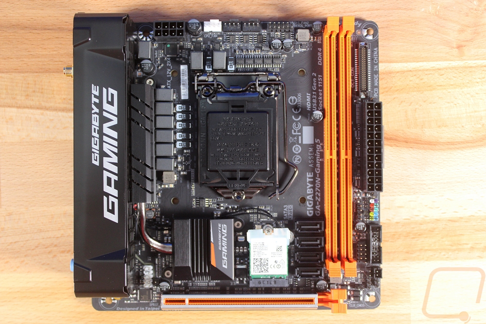
This top-down view gives us a look at the overall layout. The CPU is in the center with the two DDR4 DIMMS just a little bit away from the right edge. The PCI slot takes up the entire bottom and the I/O the left so all of the connections are packed in the top and right sides. The main two, the 24 pin motherboard power and the 8 pin CPU power are split up with the CPU power in the traditional spot up top and the motherboard power is in the middle on the right.
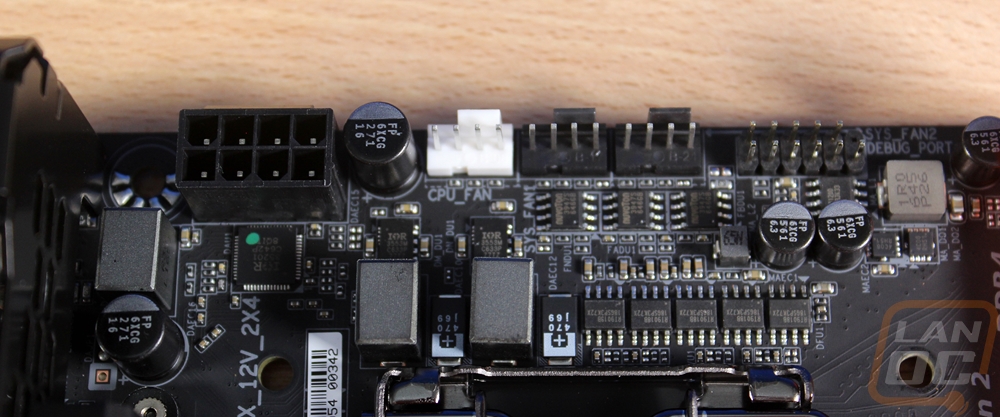
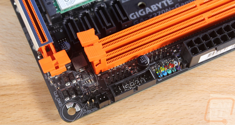
Up top next to the CPU power are three 4-pin PWM fan headers for the CPU and case fans. The header next to them is a debug header.
Down in the bottom right corner, there is a USB 2.0 and a USB 3.0 connection. Just above them and below the 24 pin power are the front panel connections. There aren’t labels on the PCB for them because of the space but each is color coded. Next to that is an RGB lighting connection where you can hook up RGB lights right on to the board and avoid having to use a separate lighting controller. Given the low number of USB connections with this being an ITX board, that is especially helpful.
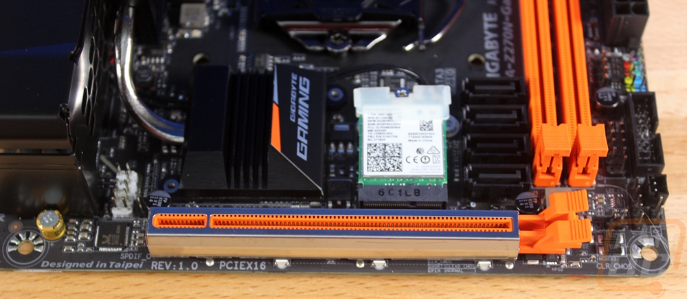
The main thing on the bottom edge is, of course, the PCIe x16 slot. It has a metal shield around it to help with interference and it also adds more durability to the slot, something that is important for a LAN rig that will get banged around. Just above the PCIe, there are four SATA connections. There is an M.2 slot that comes with the wireless adapter in it. For wireless, it covers all the way up to Wireless AC and Bluetooth 4.2 as well. The onboard audio is also tucked over in the left where you can see the front panel audio header and just a single cap. It is running the ALC1220 codec and supports 7.1 audio.
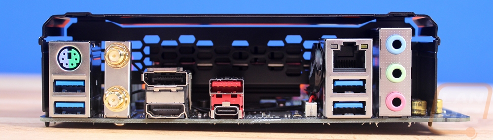
For the rear I/O connections the Z270N Gaming 5 isn’t exactly stacked. There are four USB 3.1 connections in blue and then the red Type a port is USB 3.1 Gen 2 (aka the faster connection) and the Type-C is also Gen 2. I would have really liked to see the big gap to the right have a stack of 4 USB 2.0 ports to help fill out the connection options. Once you hook up a mouse and keyboard there aren’t exactly a lot of ports left for anything else. There is a legacy PS2 port and then, of course, there are the two wireless headers to hook up the included antenna. For display options, you get a DisplayPort and an HDMI and the audio ports are cut down to just a basic three port header. In order to get the 7.1 support that the chipset supports you actually have to also use the front panel connections.
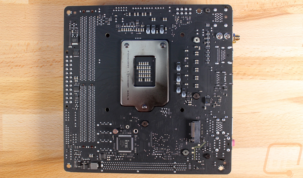
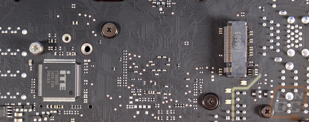
The back of the PCB has a few things going on. The back of the CPU socket has a thick metal backplate. Here we can actually see that sexy flat black PCB where up top there is just too much going on to really see it. Then there is also a single M.2 slot on the back. This allows 2260/2280 lengths and supports both SATA and PCIe based drives.