Board Layout
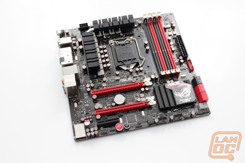
If the Gene name didn’t give it away already the Maximus V Gene is Asus’s Micro ATX Z77 enthusiast board. With the same red and black theme that we have seen on other Maximus/Rampage branded boards its clear this is a cut above what they offer in their mainstream lineup.
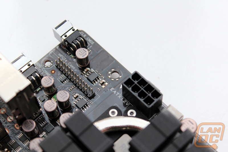
Starting in the top left corner of the Gene we have the 8 pin CPU power connection. Along-side of it there is an odd header that we haven’t seen in the past. This is Asus’s mPCIe Combo header, which goes with the adapter that we covered in the packaging section. When hooked up this gives you the ability to run an mPCIExpress card or mSATA. This means you can add your own wireless card or mSATA SSD if you would like to the Gene.
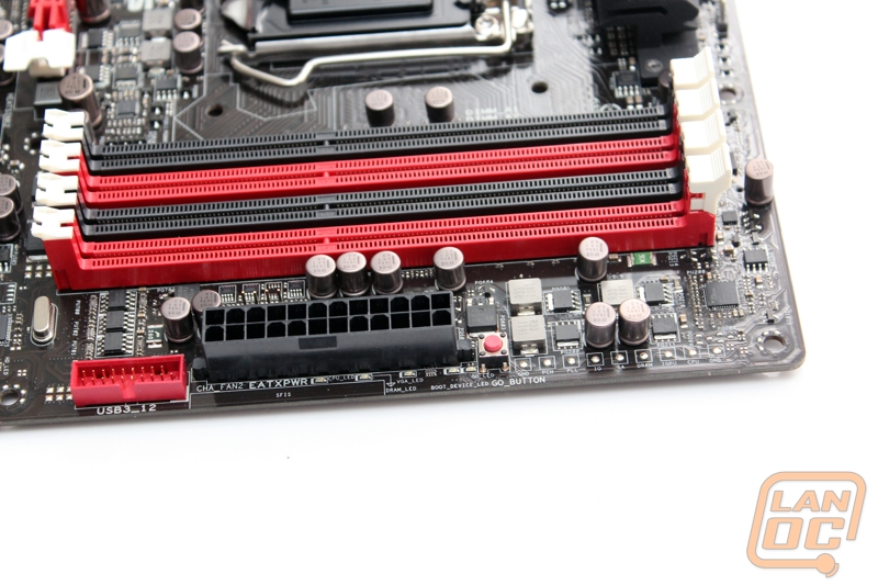
In the top right corner of the Gene next to the boards four red and black dim slots you have the boards 24 pin main power connection. Above that you have a red “go” button that is used in conjunction with profiles you set in the BIOS to hit go and turn on a specific overclock on the fly. Below the 24 pin power connection there is a red USB 3.0 header and tucked away behind everything you can also see a four pin PWM fan header as well.
On the bottom half of the right side below the 24 pin power connection and USB 3.0 header that we have already mentioned you have a total of six SATA connections. Of those six four run on the standard Intel chipset, two red SATA 3 ports and Two black SATA 2 ports. The other two red SATA 3 connections run on a different ASMedia® PCIe SATA controller. This means you can’t run four SATA 6 devices together in RAID, not that you should need to. Just below the SATA ports you also have your diagnostic LED also.
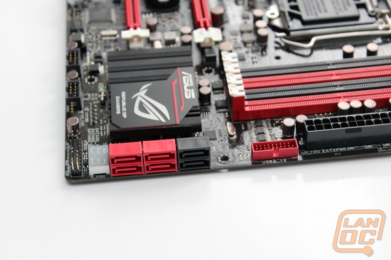
The bottom right edge of the Gene is packed with different headers. On the bottom right, below the before mentioned diagnostic LED you have the front panel header. Each connection is labeled and easy to read. I would love to see Asus go a step beyond this and color code the actual header like we have seen before, but as long as you have your eyes on you will be able to get the job done. Moving over you have another four pin chassis fan header, one of three. Then you have two grey USB 2.0 headers.
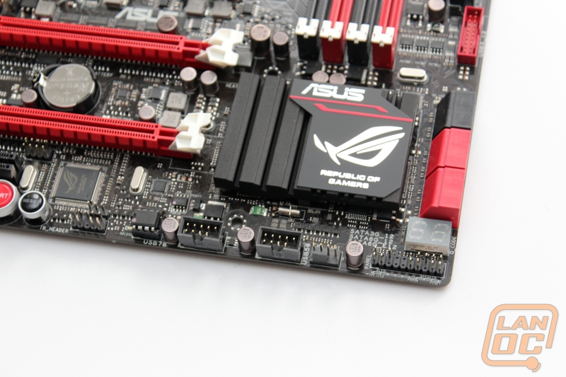
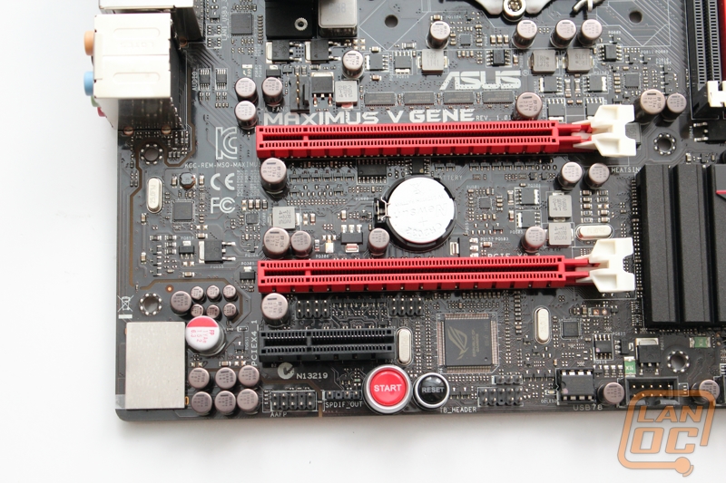
The left side of the bottom of the Gene has your front audio header on the far left. The main features of this section are the red start and black reset buttons. Both stand out and are fairly easy to read as long as you are not running a card in the last PCIe x4 slot.
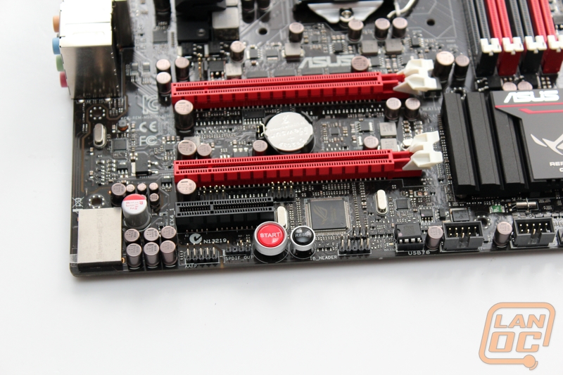
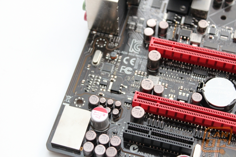
The CMOS batter is located between the boards two PCIe x16 slots. The top slot will run at x16 when running a single card and when both are used together you ended up with two x8 slots. Below them both you also have one PCIe X4 slot, usable with both x1 and x4 cards for those who might need it.
The audio setup on the Gene is unique. The SupremeFX III built-in 8-Channel High Definition Audio is on its own split PCB that is defined by a yellow line between the audio PCB and motherboard that also glows when the board is on. Splitting the PCB up like this helps prevent interference from the motherboard, this is the same reason a lot of people go with separate audio cards. Asus didn’t miss anything, even making sure the split PCB goes all the way around the front audio connection.
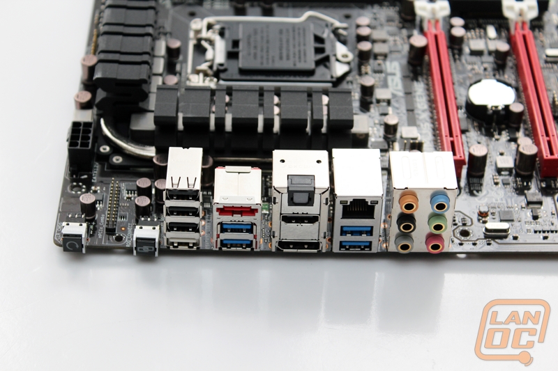
For the rear I/O panel connection you have the 6 audio connections running on the SupremeFX III built-in 8-Channel High Definition Audio card. For USB connections you have eight connections on the rear on top of the USB/eSATA connection. Of the eight USB connections, four are blue USB 3.0 ports and the others are USB 2.0. There is one white USB port that doubles as a USB 2.0 port as well as the ROG connect connection. For onboard audio you have display port and HDMI as well as an Optical S/PDIF port.
Although it doesn’t have the Intel NIC sticker we have come to expect on Asus boards, this board does come with an Intel Gigabit network card built in, something that most other boards don’t go with to save money. On the left side of the rear I/O you have the CMOS reset button and the ROG connect button. There is a gap where the mPCIe header is, on the actual IO panel there are two spots for you to run two wireless antennas out if you decide to go that route.
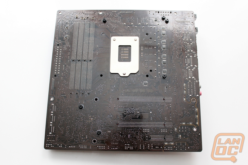
It’s interesting to look at the back of this board more than most that we get into the office due to its smaller size. If you look close you can see the track routes are just packed in, something that is less obvious on larger full ATX boards. You can hardly see the boards black PCB. There are so many trace routes that the board almost has a copper color.