Board Layout
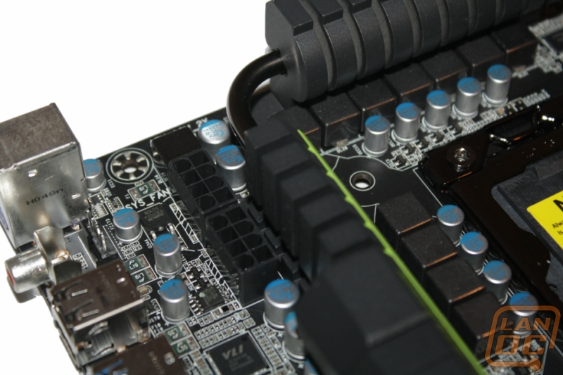
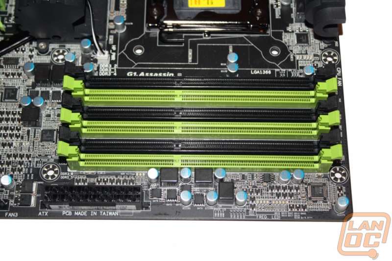
Starting in the top right corner of the board, Gigabyte colored the six 240 pin DDR 3 slots in black and green to match the cooling system. Between the closest ram slot and the heatsink you have about a half inch clearance. This should be enough to keep tall ram sinks away from large heatsinks unless the heatsink overhangs over like the V10 from Cooler Master. You will also find the 24 pin main power connector in this area close to the edge of the board for easy wire management.
The bottom right corner, you have the front panel connections in a color coded box near the bottom right corner, a perfect place to put them and keep your wire management in line. You will also find a four pin fan header tucked between the front panel header and the corner. With two USB 3.0 and two USB 2.0 headers you shouldn’t have any trouble with USB connections. It’s also great that they included two USB 3.0 connections, this way if you use the front panel device they include with the board you still have a connection for your case’s front panel USB 3.0 ports. Also in this area is the connection for the front panel devices overclock button (the white 5 pin header), and also the Clear CMOS header (above the black USB 2.0 header). It’s nice to see the clear CMOS header in an easy to reach location.
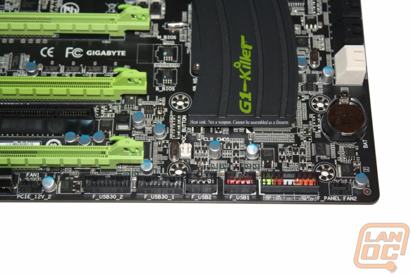
I also wanted to point out, look at how close everything is packed together on the PCB. Even with this being an XL-ATX board they still needed every inch of space to pack everything in.
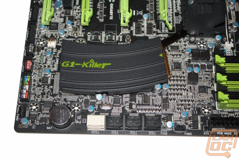
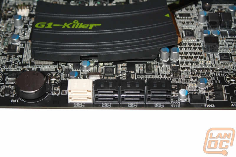
Also in the bottom right corner are 8 SATA connections (2 SATA 6) and a four pin fan connection
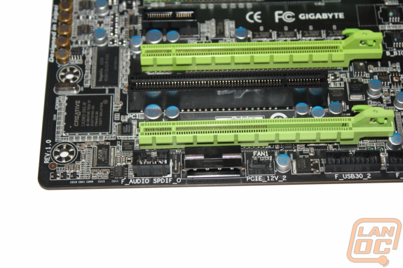
The Assassin can run four video cards in crossfire or three in SLI using its four PCI Express slots. Of course when filled only two will run at a full 16x, the other two are limited to x8 each when running four video cards. The top and third down are full x16, the second down and bottom slots share a x16 connection between the two of them. You also have two PCI Express x1 slots and one legacy PCI slot. Also of note are the two Molex connections needed to power everything. I found that it was very hard to use one cable to reach both of those connections, although it could be done. It would be nice if they were closer together.
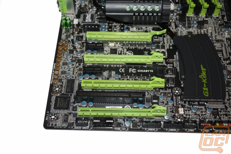
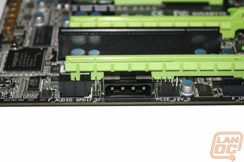
I do like that they used a right angle connection for this Molex connector. Details like this make wire management easier. Although I think they only reason this is right angled is for clearance if you use a dual width card in that last slot.
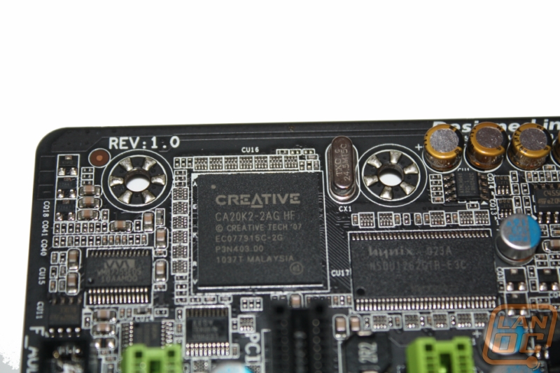
On the bottom left you can spot the Creative Soundblaster X-Fi Digital Audio Processor
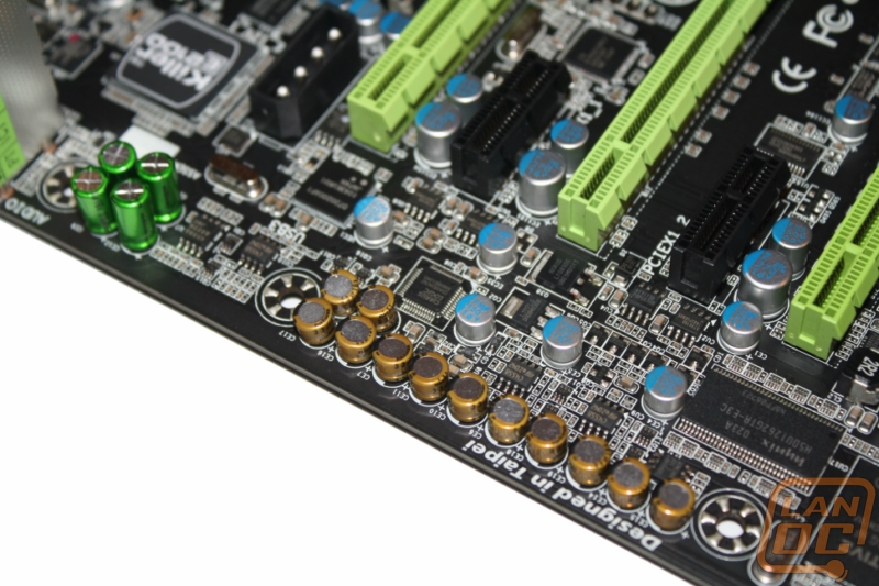
Just above the Creative onboard chipset you can see the Nichicon capacitors used for the 5 different amplifiers uses on the Assassin. The 5 amplifiers are used for the following. Front panel headphone plug, center/subwoofer, rear speaker, side surround and line out. This is a drastic change from what you would find on any other motherboard!
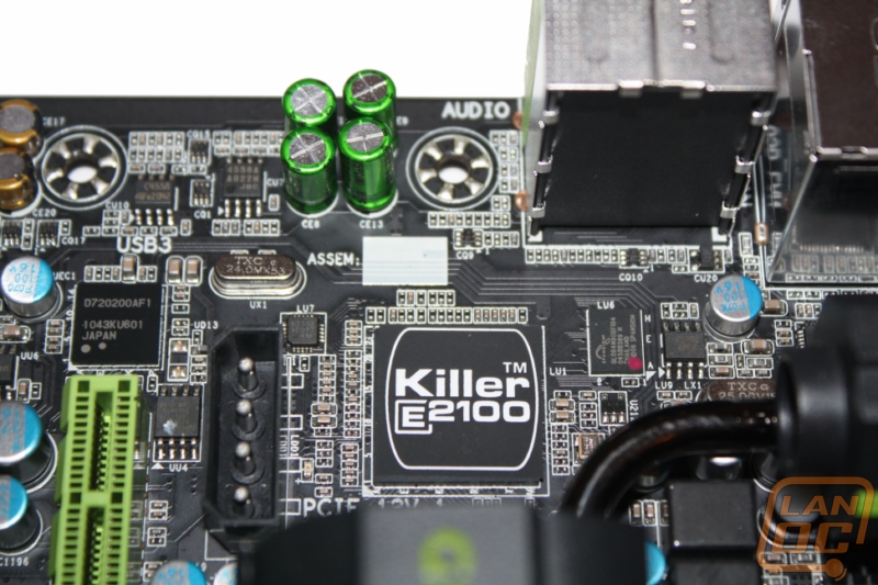
Tucked away just under and behind the read I/O panel is Bigfoots Killer E2100 Dedicated Network Processing Unit along with 128MB of dedicated DDR2 memory. How many motherboards can say they have a gigabit of ram built into it, not many ;)
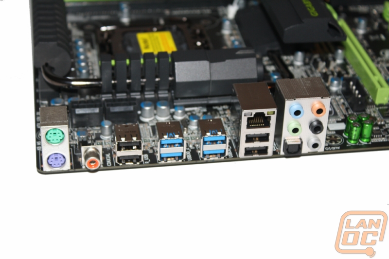
And last but not least you have the Rear I/O panel. With a feature set as long as the Assassin’s its surprising to see how bare its I/O panel is. But they designed everything about the G1 Killer series specifically for gaming, and gamers don’t need multiple NIC’s onboard video, firewire, and all of the other connections we have seen on other motherboards.