Building your Ergodox
As you might have figured out from the packaging photos or even “Kit” in the product name the ErgoDox comes in pieces and you have to put it together. You are going to need a short list of things in addition to the kit itself to be able to get it all together. Here is a short breakdown:
Soldering Iron with a flat tip
.032 Solder
An area or surface to work in
Wire cutters
Diagonal cutters
Tweezers
Time
Before I got started on this build I had to go out and replace my old soldering iron because it was dead. I went with a temperature controlled Hakko Digital FX888D but you could go with something cheaper as well. For solder I went with Kester 44 Rosin Core Solder 60/40 .031, I picked up a full spool because I couldn’t find anything on how much I should expect to use but looking back you could go with one of their small kits and save money. To prevent any damage to my table when soldering I picked up a silicone baking mat for cheap on Amazon to work on. Once I had everything I needed to get started I spent a little time practicing my soldering and also reading both Massdrops instructions and also an additional set of notes over at studioidefix. To give you an idea of my soldering experience, I used to solder a lot when I was younger and raced RC cars and again later when I spent a lot of time working on cars as well but I haven’t soldered anything at all in at least 8 years. Because of that I was careful to watch a few videos on YouTube and also practiced soldering before getting started on the ErgoDox.
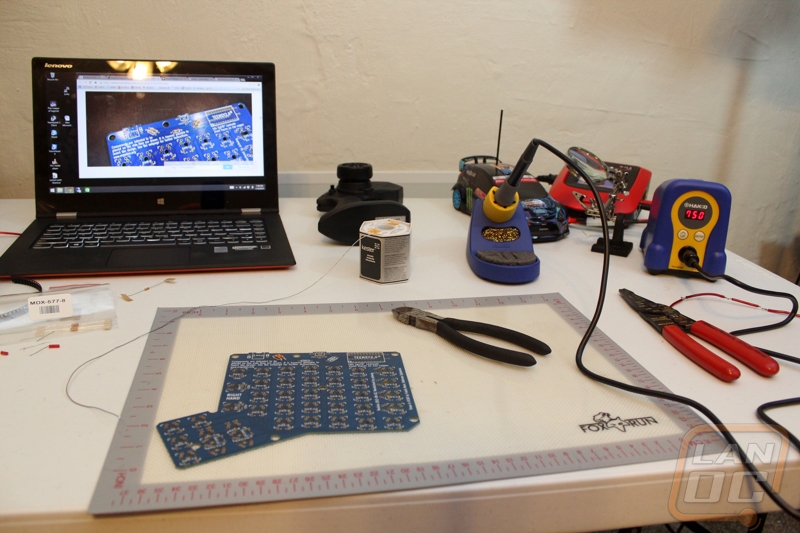
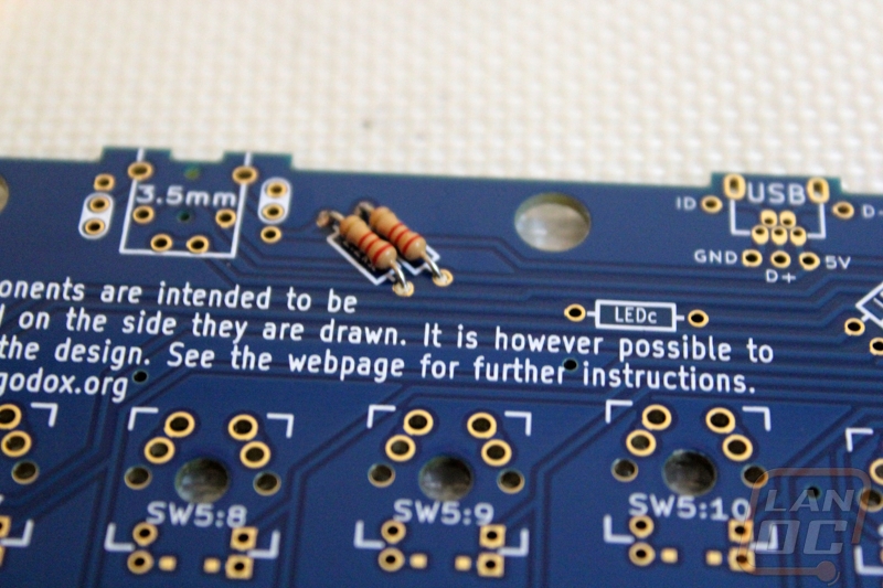
While officially Massdrops instructions start you off with the diode installation. I started by installing the resistors first to get a little more comfortable with things knowing that the diode installation was by far the hardest art of the build. They make things easy to figure out though. Both PCBs are the same but when you flip one over to be the second hand you will see they did a great job with highlighting what you need to do for each hand right on the PCB. For example on the resisters they put boxes around the mounting locations with labels inside on the right hand side and the left hand side has nothing.

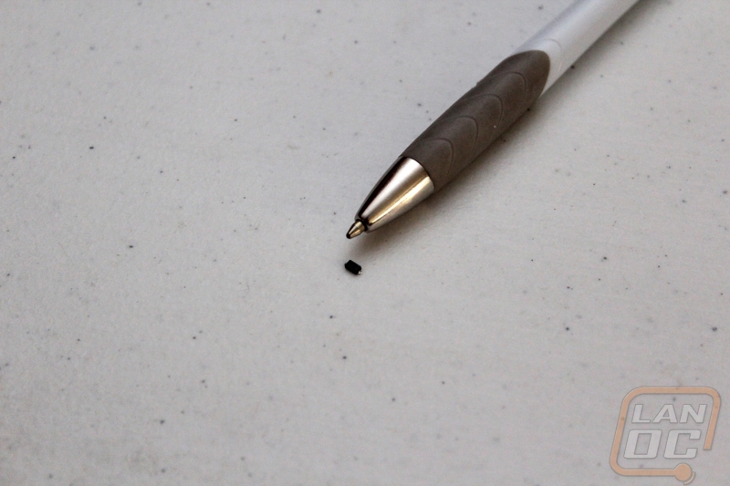
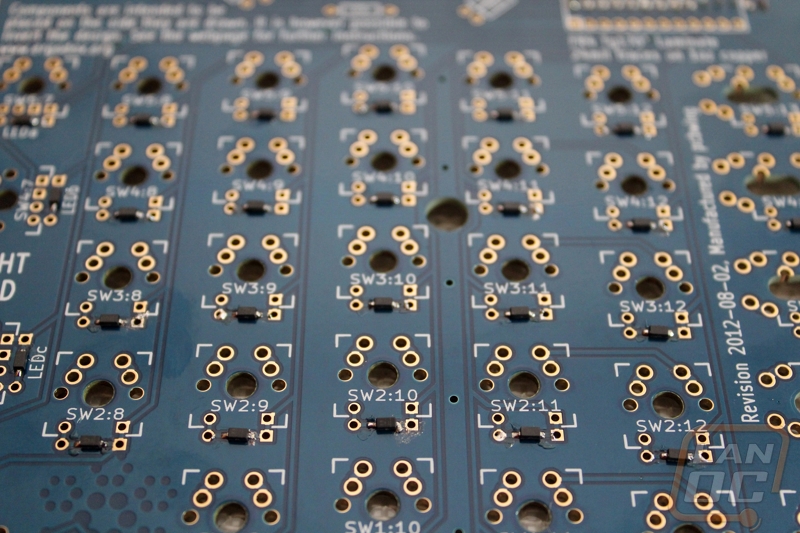
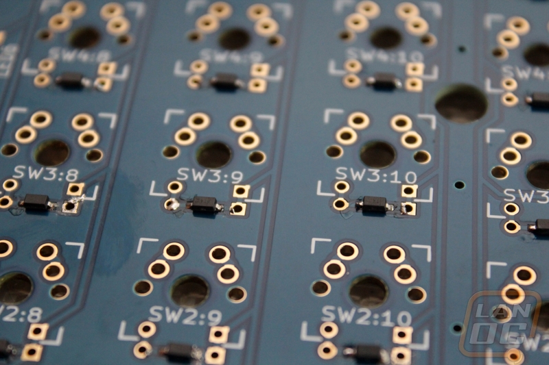
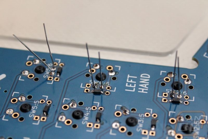
Once I was comfortable I started in on the diodes. As I mentioned before this is BY FAR the hardest part of building the ErgoDox. This is because the diodes are ungodly tiny and they are surface mount. Even going into the build having seen the build photos on the Massdrop website and YouTube video of a build I was shocked at how small the diodes are, I took a picture that really shows their size. They are the size of the tip of my pen. To make things even harder there is a polarity so you have to look for a line etched on the top and put that side on the side of the switch PCB with a square. The best way to do this is to tin that side first, find the polarity, put the diode down lined up, then solder that side first. Once you have that side down you can come back and solder the other side.
Due to their size, the first whole PCB that you do will take a while but the second one will go very quickly once you have the hang of it. Sadly for me I messed up bad on my first PCB. When I originally read the instructions, I thought they wanted the line side to be on the square pad and in this case one of the pads looked square and the other had one side slightly rounded. When I moved on to my second hand I figured out that they wanted it to be on the side with the square with a hole in it. So I ended up having to go back and remove every diode and flip them all over. If you think putting the diodes on is hard, putting them BACK on it even harder because you have solder on both sides. I did manage to get it all put back together but my resoldered joints didn’t look half as good as my second PCB.
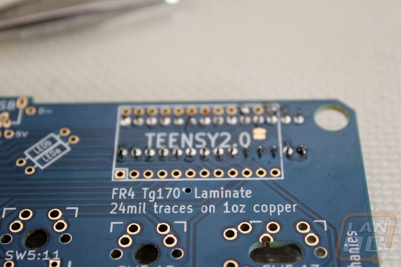
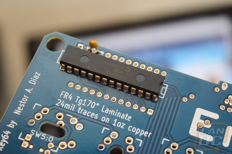
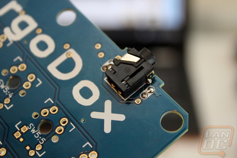
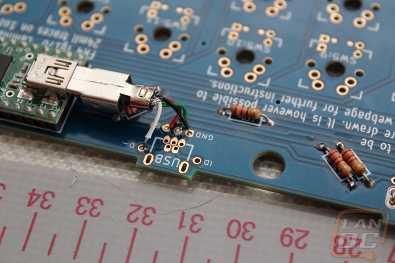
Once the diodes were finished everything else started to come together a lot quicker. You have to solder down the I/O expander as well as the capacitor to clean up the signal. Both boards need their TRRS connectors installed as well. This is just a small headphone jack that communicates between the two halves. Then on the right hand you solder on the Teensy V2 USB board that will run our firmware. Before doing that I did save myself a little trouble and I plugged it into my PC and used Massdrop’s instructions to flash the firmware.
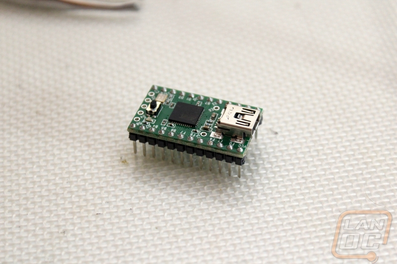
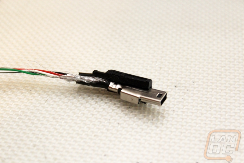
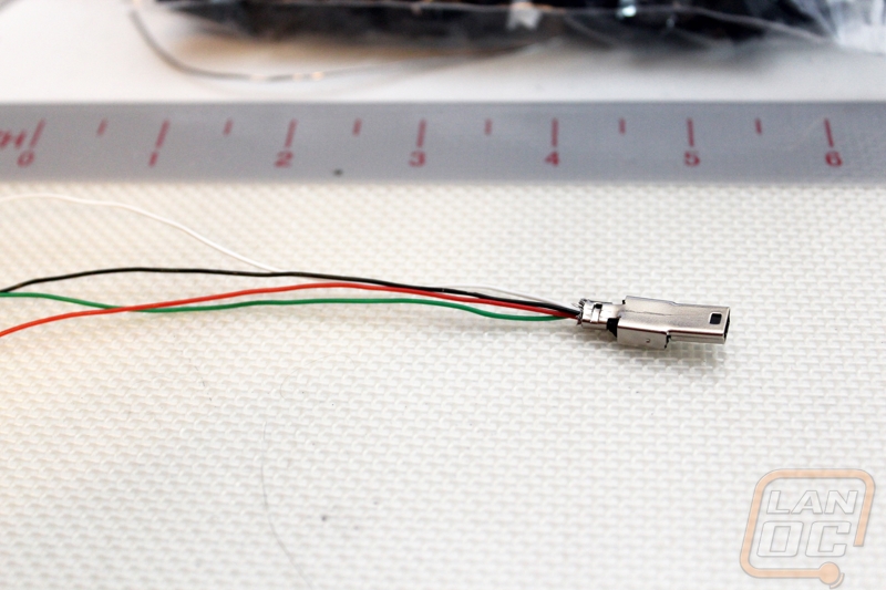
Once you have the Teensy installed you have to cut and rip apart one of the two USB cables that is included with the ErgoDox. This seems a little weird but the USB connection on the Teensy doesn’t face out so we need to run the USB onto the PCB and then install our actual USB plug. Massdrop suggests that you use a Dremel to get the thick casing off of the USB connection but I managed it with a box cutter. Once you get it apart, you have to cut the leads down a little more and strip them. Then you solder them in the four labeled holes around the USB connection on the PCB. Be sure to give yourself a little extra room just in case you mess things up, if not you will have to get a second cord to cut up and start over again. From there you install the USB mini B plug. Be sure to give extra solder on the side mounting points to give it a little extra security.
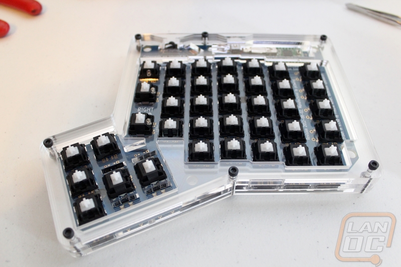
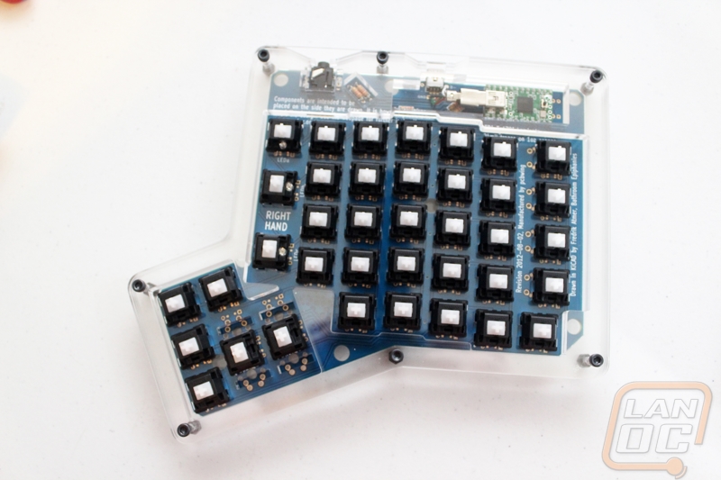
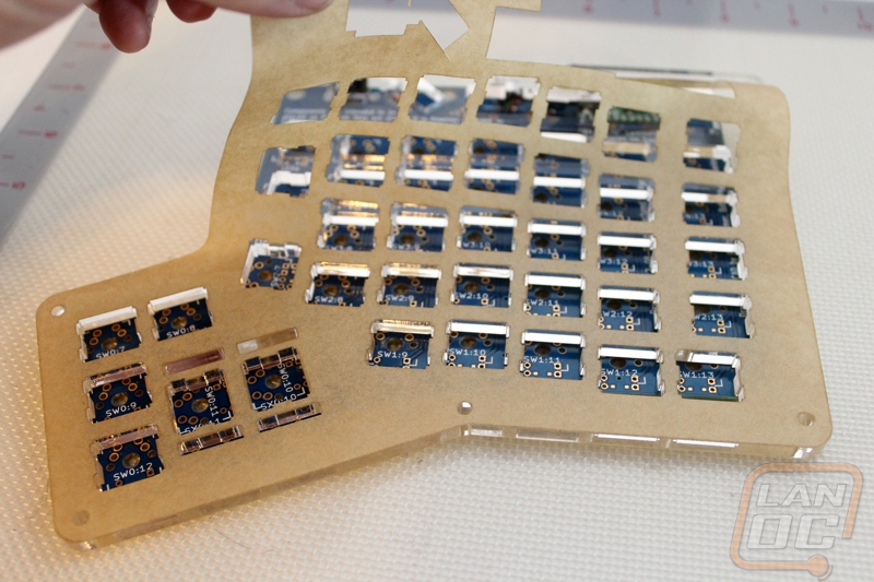
Next you need to dig out the 3rd layer of acrylic for each side, the switches mount to the plate and the PCB at the same time. You will have to pull the protective coating off as well. Here you want to start by doing two switches with one on each end. Getting two in properly will keep everything together tight for you to do the rest. Basically the switches just push in but make sure the pins on the back aren’t bent, I had a few. I installed all of the switches on the left hand and all but the three LED switches on the right hand then flipped things over and soldered the two pins of each switch. This has to be the best part about the build because for the first time everything is starting to come together.
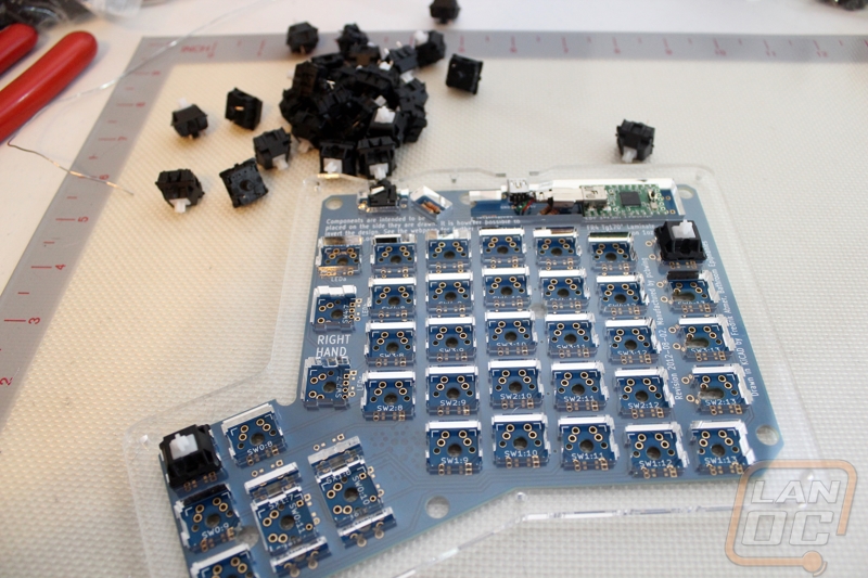
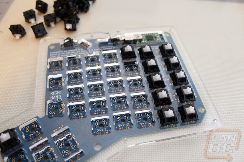
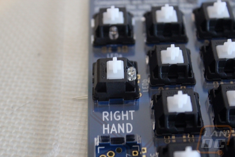
The three LED switches install the same as the others but you have to also slide the LEDs into the LED slot on the switch making sure to take into account the polarity of the LED as well (the longer lead is the positive side). When installing these you have to pull on the LED as you are soldering it to get it pulled tight.
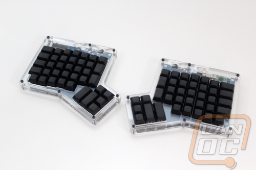
With everything together, before I put the casing together I hooked both PCBs up and went through and confirmed that every switch worked. I found 3 that had problems when testing, noted their locations and went back over and took a closer look at them. Not surprisingly on the side that I had to redo all of the diodes a few of the diodes didn’t have a good connection. I went back through them and then confirmed it was all fixed. From here I just had to pull all of the protective paper off of the acrylic and stack everything together. Massdrop includes the 6 nuts and bolts needed for each PCB. I should also note that they do provide a few extras of everything including a couple extra switches just in case you run into problems. So once I had the ErgoDox together I put together a small bag of extra backup parts. All in all I spent about 2 and a half or three hours building everything but far too much of that was spent redoing my work over. If I build a second one I think it would take an hour to an hour and a half.