Packaging and Assembly
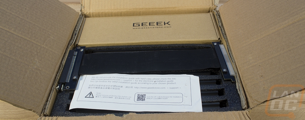
Okay, so one of the quirks of the A30 is that it comes flat packed. This isn’t the first case that I have had come this way, Case Labs does the same thing on some of their models. But the A30 is a little different, this case uses an aluminum extrusion frame. So this isn’t a simple attach the panels together. This is a lot closer to building some of our 3d printers. GEEEK even warned me ahead of that that this is flat packed and that it is an acrylic and extrusion construction. I suspect some members of the media are turned off from building their own case, but longtime readers will know I LOVE building things like keyboards from scratch, our 3d printers, and all of the 3d projects. If anything I end up loving things I have built more. So the flat packed box with GEEEK on the side wasn’t a turnoff, it was more of a challenge or an adventure waiting to happen.
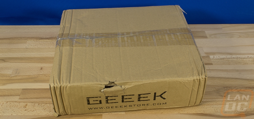
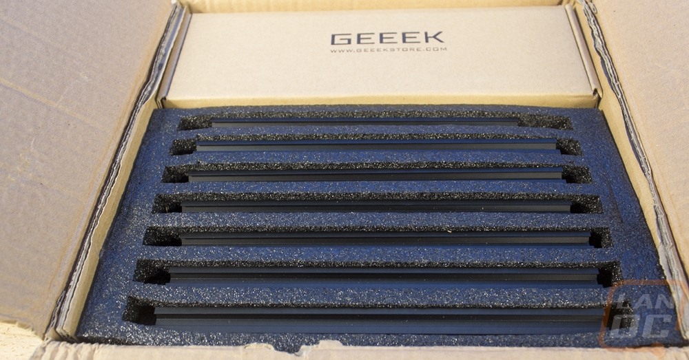
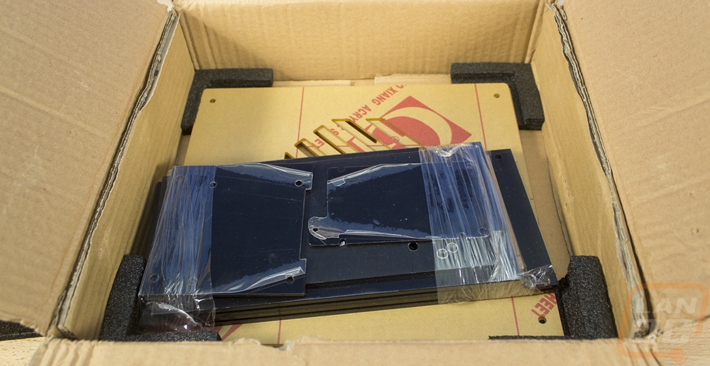
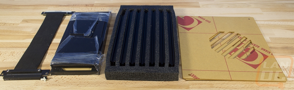
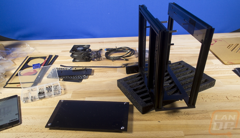
So inside the box, the PCIe riser (that is sold separately) came right up on top. Below that was a foam tray with slots carved into it for each of the aluminum extrusions and then another box. Up under the box and foam were all of the acrylic panels. The largest ones are on the bottom with foam in the corners to protect them. Then the rest were all wrapped up together to keep them from moving around. All of the smaller panels also have a plastic on them and the two side panels have a paper attached. Both will be peeled off to build, my fingernails aren’t looking forward to it.
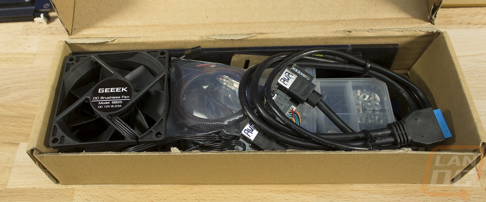
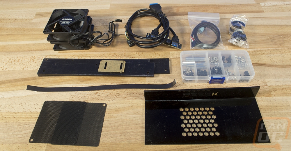
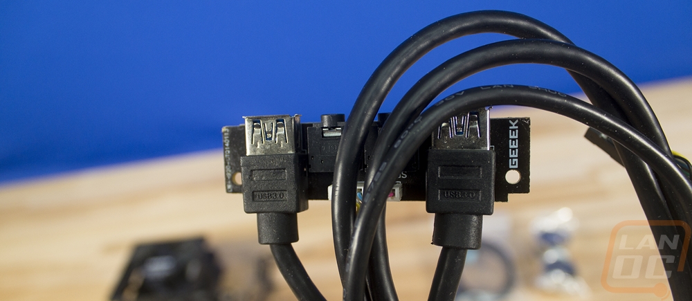
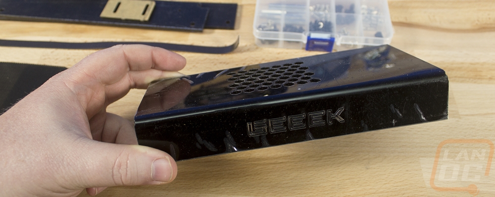
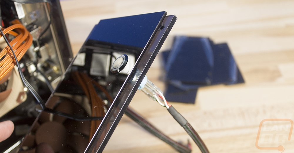
So the box that was inside of the box has basically anything that isn’t main structure inside of it. This includes the two fans and fan filters that are add-ons. The large PSU cover is also an add-on as well. Of interest though is the small plastic tray that comes with all of the screws, standoffs, and other mounting hardware. There is also a standard vandal LED switch for the power button, it has a black sleeved cable. And the front panel I/O with its two USB 3.0 connections and HD Audio. This has a PCB with the GEEEK branding on it and both cables are covered in black rubber. The audio does still have the colored cables visible at the end of the cable though.
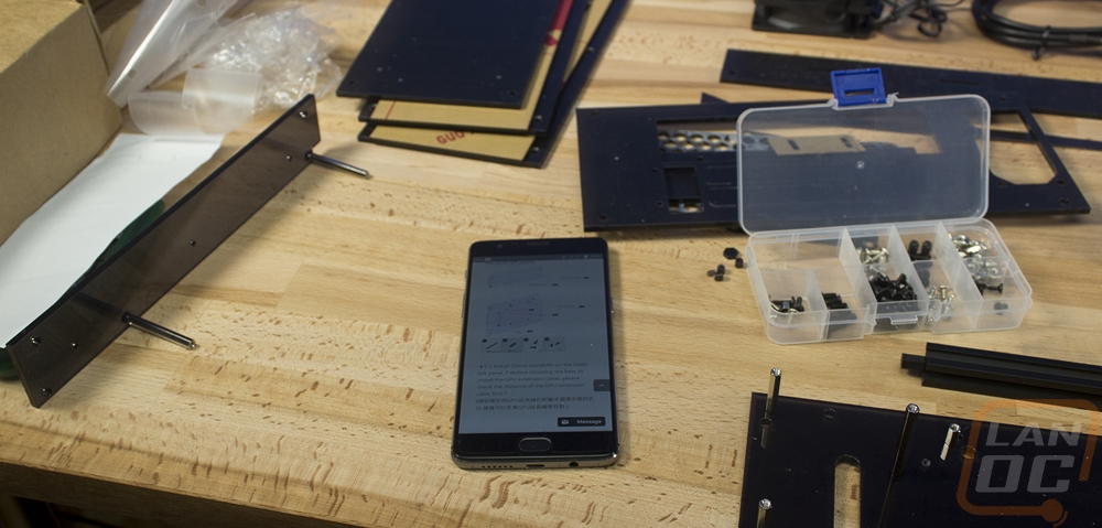
So with all of the components out and sorted through I could start building. I got the hardware tray out and kept that close and I used my phone to pull up the online building instructions. I would normally use a laptop but I didn’t really have the extra space in my work area. So this is where I ran into some confusion, the GEEEK website has two sets of build instructions labeled 1.1 and 1.0 but I don’t know what version our kit is. There is also a 1.2 listed currently that doesn’t have its own instructions as well. But no worries I can figure it out (I hope). I started off with our first panel, the bottom half of the motherboard backplate.
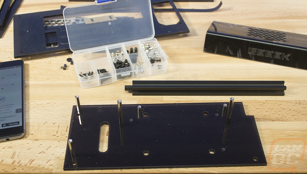
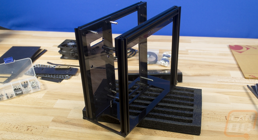
The next steps had me putting that panel as well as a second panel together with four different extrusions. It is really important that you take a look at the separate instructions with tips on connecting these extrusions. Getting the clamps locked into place wasn’t exactly the most fun, I think GEEEK could take a few tips from the 3d printing communities designs that have t-slots that fill the entire extrusion. The included t-slot bolts work but like to spin around when you are tightening them. Anyhow this section I found myself doing a few times when one clamp would spin, even when together it is all a little loose until the whole case gets together so be careful.
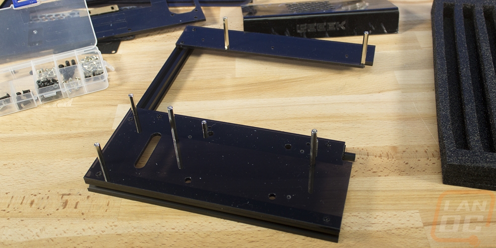
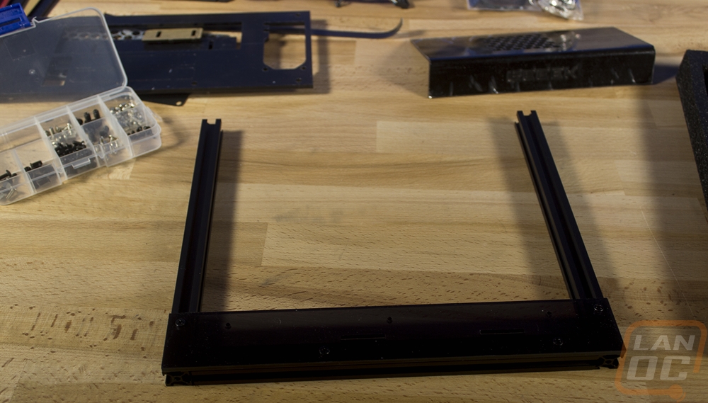
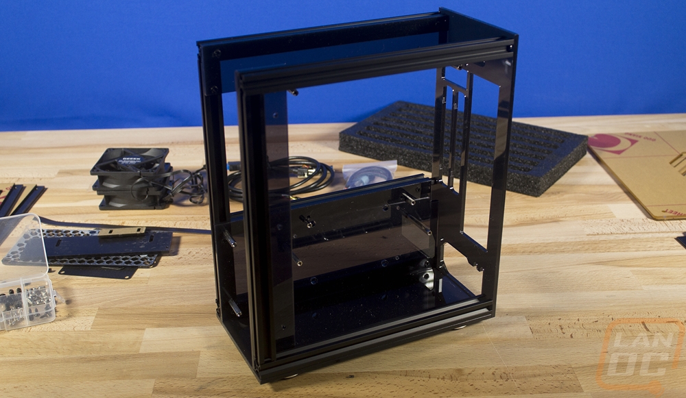
Then you work on the second half of the frame. It is three extrusions and just one small acrylic panel. Once together we just have to get one panel out to connect our original frame and this second half together. Once together it is almost looking like a case, well the frame of a case at least.
Next, you attach the four included feet to the bottom panel. Then you prep it with four screws and t-slot nuts and you slide it into place. Now we have the rear I/O area together and the bottom. This is the piece that finally holds everything together solidly. You can finally not worry about it snapping that rear panel in half if you bump something.
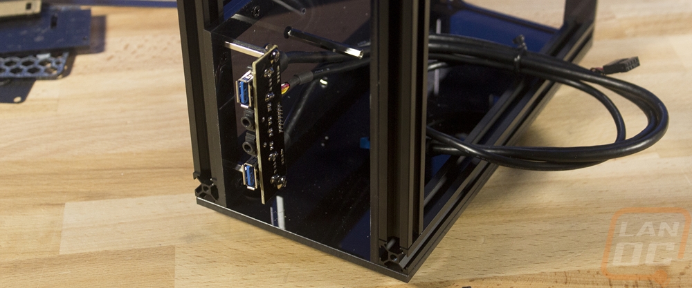
Next, they have you put the front I/O in. Much later in the build, I find out that I have the wrong standoffs here, they should be shorter and put the I/O up against that extrusion on the left so don’t worry too much if yours looks a little different. Getting these two screws in is a little tight. You have to go at an angle so be extra careful not to cross thread them.
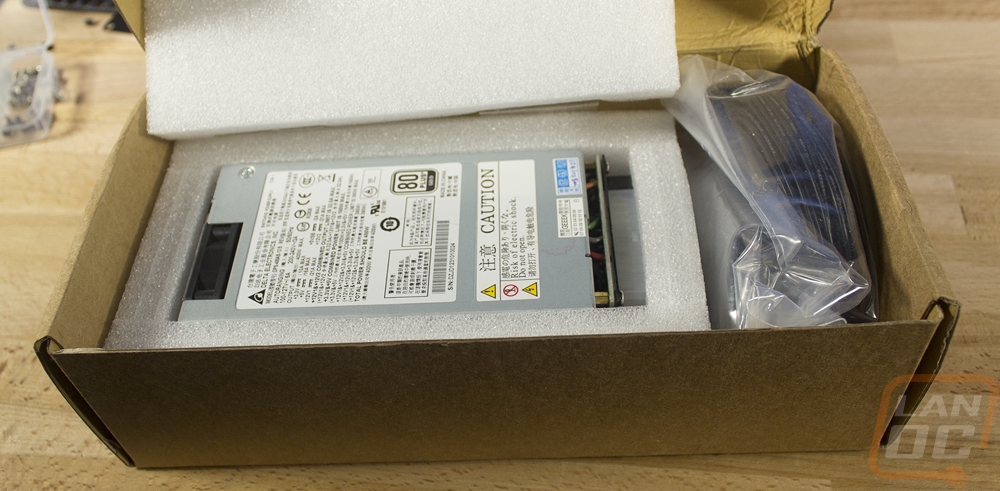
Next GEEEK wants you to get the power supply installed. When I first reached out to them about this case I came to the conclusion with my research that none of the Flex ATX power supplies on the market were going to work for me. Obviously, they had reached that point as well because they sell a modified FlexATX PSU as well. There are a few things, first, we need enough power to handle a decent PC. In addition to that, because of the size of the build, there isn’t room for a bunch of extra cables, and typically FlexATX power supplies are for server use and are very loud. So their modified version has the fan replaced with a quieter fan and modular custom length cables. You can even pick the cable color! So the PSU actually comes in its own box away from the case. It is wrapped up in foam and then all of the cables are in their own bag at the end of the box.
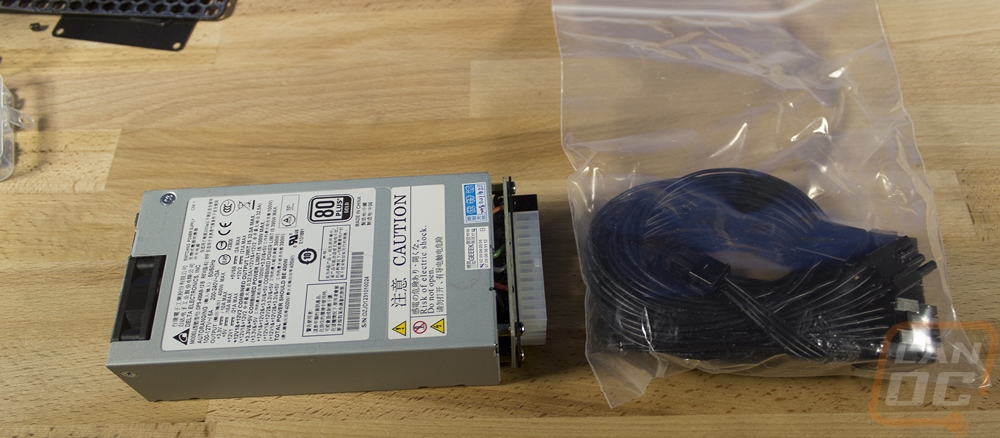
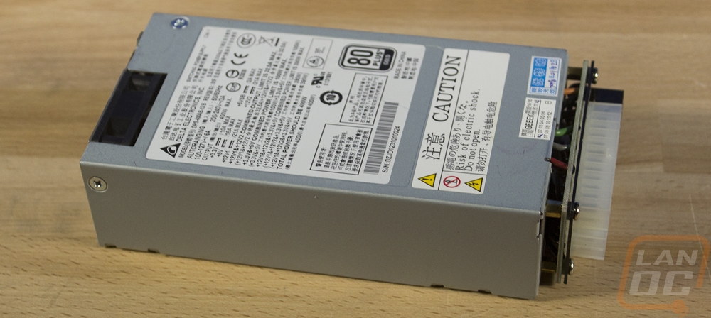
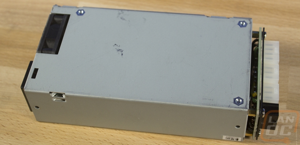
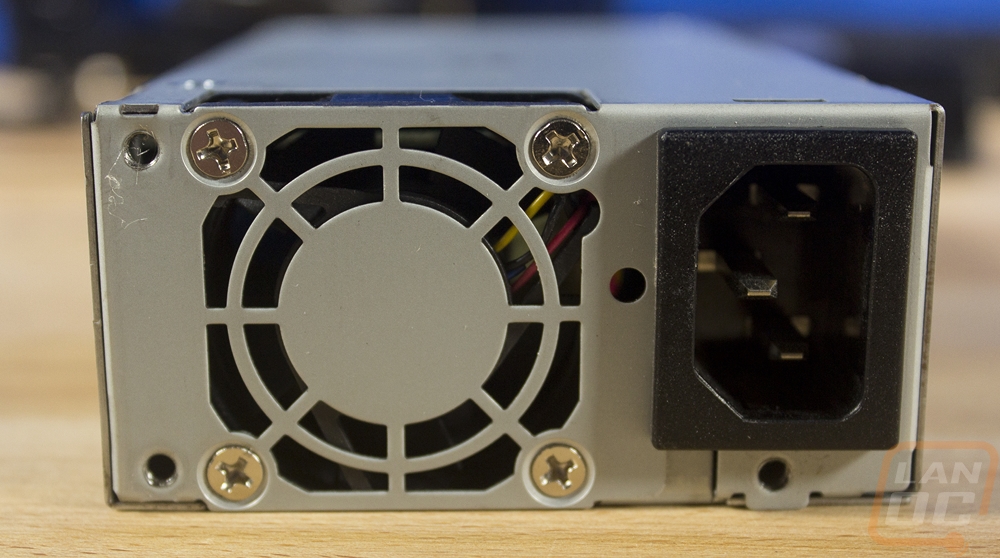
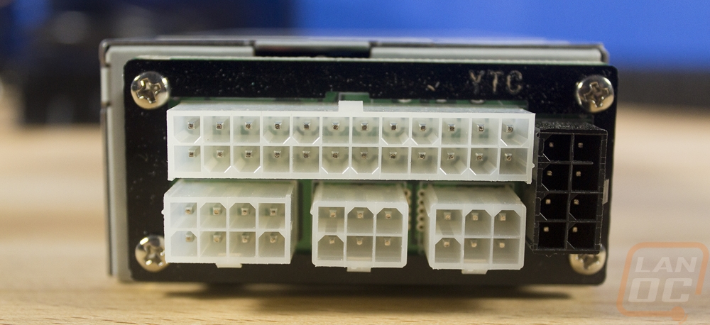
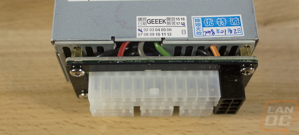
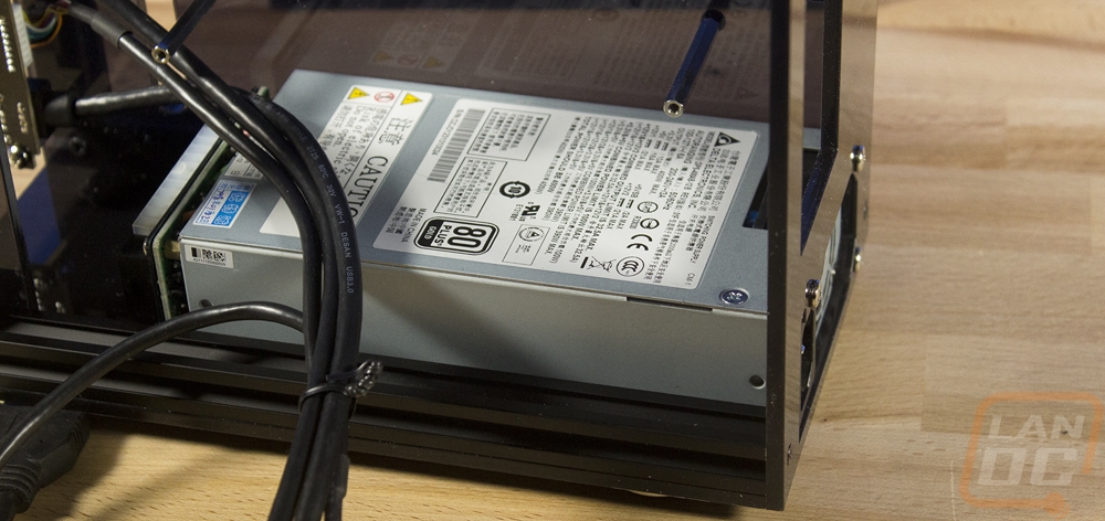
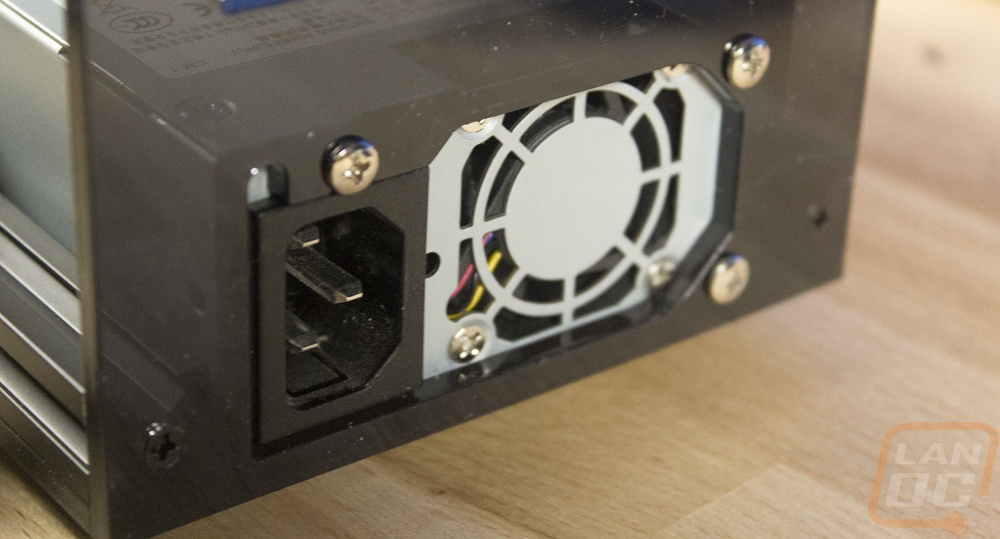
The PSU isn’t spectacular looking, it is your old school bare metal look. GEEEK mentions in their listing that they aren’t used, but you can expect a couple scuffs and ours did have that. No surprises though, this is a basic PSU that has been opened up. Scuffs are going to happen during that process. Anyhow if you haven’t seen a FlexATX before, they are a lot thinner but longer. You can see that the ends barely fit the fan and power plug on the one end, that’s also why noise is normally a big issue. You have such a small fan, so higher RPMs are needed. The modular end has a new PCB on the end with four connections. You have a 24 pin, an 8 pin CPU, one 8 pin for the PCIe cable, and then two connections for Molex and SATA cables. That’s all you get with SFX and all you need for any build this size really.
On the plus side of things, installing the power supply is extremely simple. Being modular meant I didn’t have to fight with any of the cables just yet. There isn’t a fan on the bottom so it drops right onto the bottom panel and fits snug between the extrusions so you just have to slide it back against the back and put in the screws. The power connector was tight but fit. I may want to pull it out later and paint the fan area so I don’t have to look at that grey/silver finish. To handle the rest I went with the optional PSU cover. I install that later, the instructions don’t actually mention when or how it is installed but I will talk about that later.
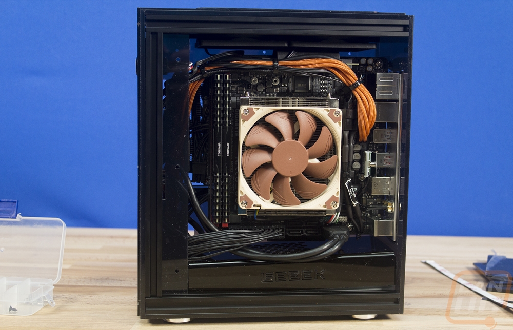
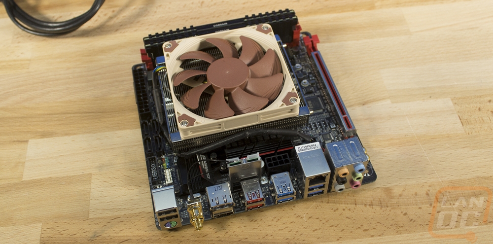
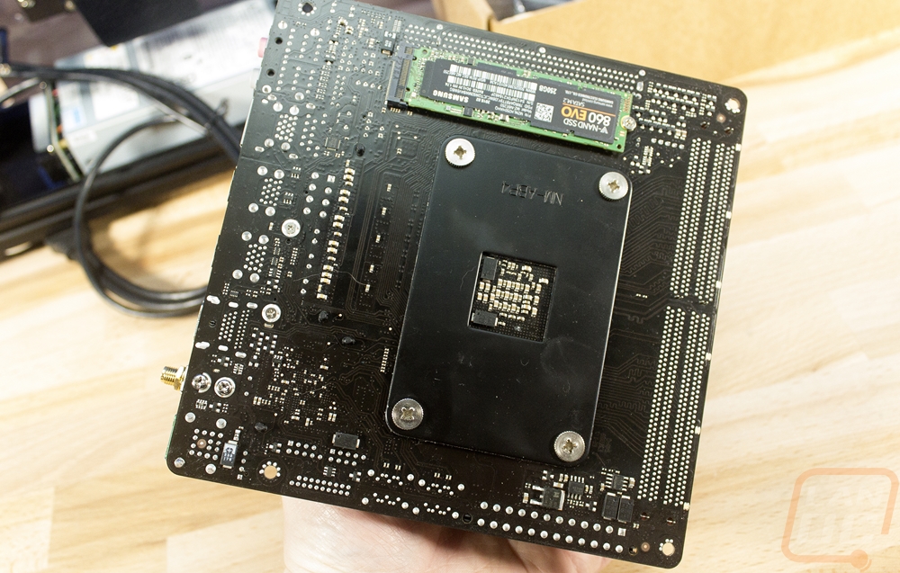
So the next step is getting the motherboard installed but before doing that I have to get it all prepped. That means getting the CPU installed, the heatsink, ram, and in our case the SSD as well because I went with an M.2 drive. I went with the Gigabyte AB350N Gaming because it has been our go-to ITX Ryzen board. I was originally planning on testing with an Intel CPU but frankly, the A30 doesn’t have a lot of heatsinks that fit. The overall clearance is 50mm so the Cryorig C7 is the obvious choice but I have ours currently being used in another build. It just so happened that Noctua sent a new NH-L9a-AM4 cooler and what a good place to test it out. So from there, I had to decide what CPU would best fit our situations. Obviously, heat is a big concern in small cases like this, but I want/need gaming performance so I went with the 1600X Ryzen 5 CPU, its 95-watt TDP just barely stays within the range of our cooler and 6 cores with a 4GHz turbo is a monster for an SFF build! For memory, I just went with the Corsair Vengeance kit that came with our original Ryzen launch because it was low profile and has great Ryzen support. Then for testing the SSD was just the 256GB Samsung. If I stick with the A30 in the future the 1TB WD Black might be calling its name.
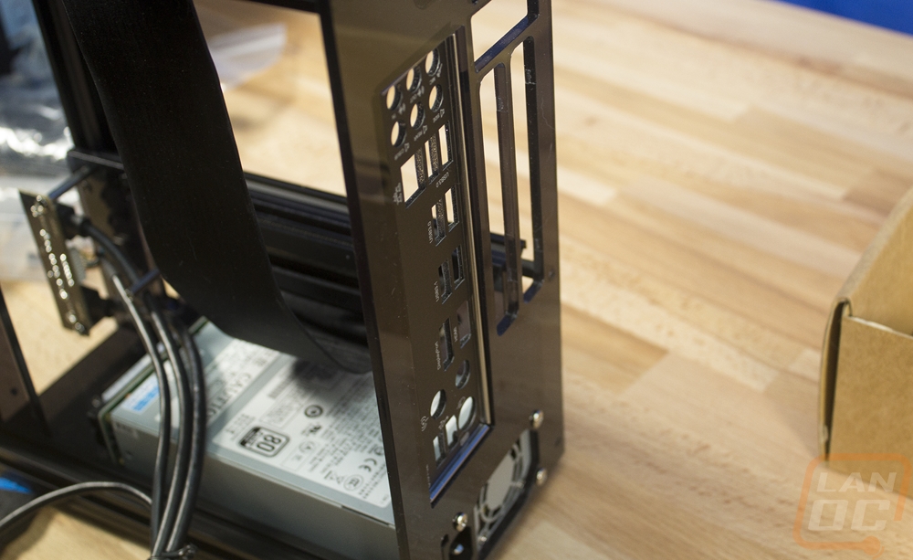
So it's not mentioned in the instructions at all but I did find that the rear I/O panel did fit. It doesn’t fit snug but once the motherboard is installed it will hold it in place. A lot of these custom builds, or even a lot of the less custom cases from In Win don’t have I/O panel support so I was happy that it did work here.
Getting the PCIe riser installed was really tight. As it turns out, I had mounted the bracket with the wrong standoffs so I think that made some of the difference. But even later with the correct standoffs, this is a tight fit. It is easier to install it into the board then to slide the board up and install it after. It looks great once installed though.
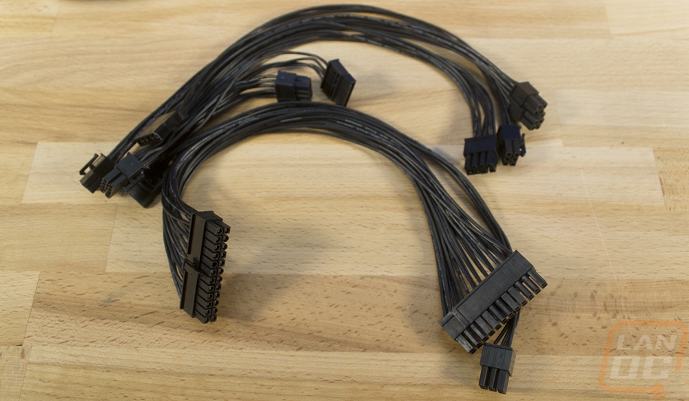
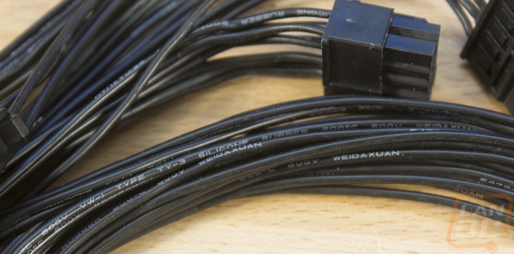
This is another step that isn’t mentioned at all in the instructions. But after looking ahead I found that getting the cables all installed and ran now was easier than waiting until after the video card was in or anything else. This was my first look at the cables that GEEEK provides and I love these. There isn’t any sleeving to stiffen or thicken things up. The cables are all black (but available in other colors) and thin and flexible. This is huge for an SFF build, most are a pain to work with. These are even a lot thinner and more flexible than the flat cables that some PSUs use for some cables. The silicon rubber used here is great.
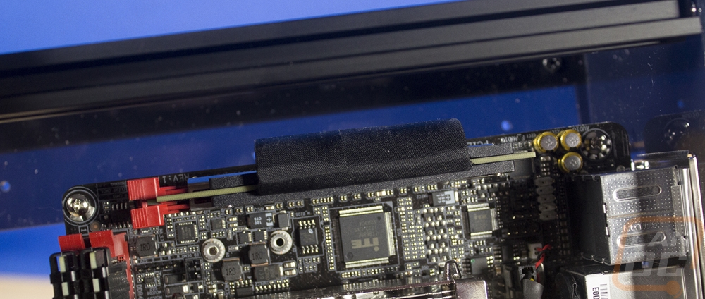
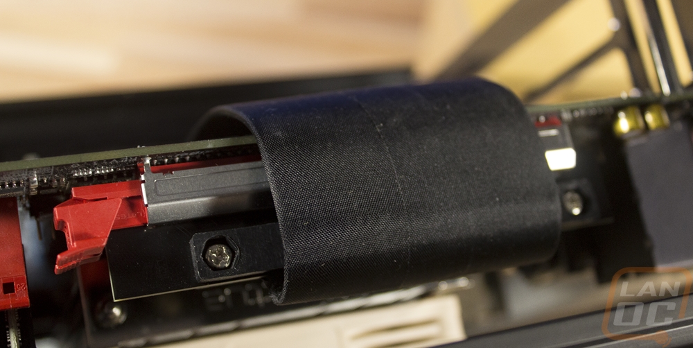
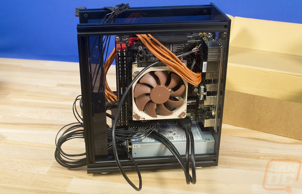
Running the cables is going to be a challenge in any SFF case and this wasn’t much different. The main issue I ran into was because of the odd placement of the power connections on the Gigabyte board. I didn’t initially plan to use this board, had I known I would have asked for a longer 8-pin cable. So I had to dig out an extension cable (actually I stole it from one of our test benches, I’m going to hate myself later for that one) to hook that one up. Of course with all of that extra length now I had too much cord.
While doing all of this I figured I better get the PSU cover installed as well. I really wish they had instructions included. I just dropped it in place and it fits snug most of the time. There is a strip of magnet that I suspect is actually for installing this to the top of the PSU but because I wasn’t sure I didn’t use it. That said, it makes a huge difference in the look of this build. I would not go without it if you buy an A30.
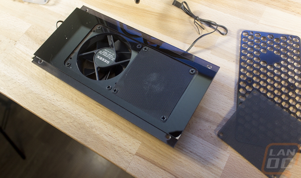
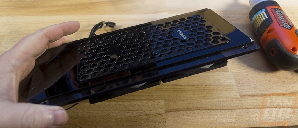
Next, you have to get the whole top panel altogether and prepped. This includes installing the two optional 80mm fans. There are also optional fan filters, this is another one of those situations where I’m unsure if I have them installed correctly, basic instructions for the optional stuff would be awesome. The top panel sticks up a touch so I suspect that I need to pull this back apart and put it together correctly or I need to bevel the screw holes to get them to fit a little lower. I love the honeycomb grill though!
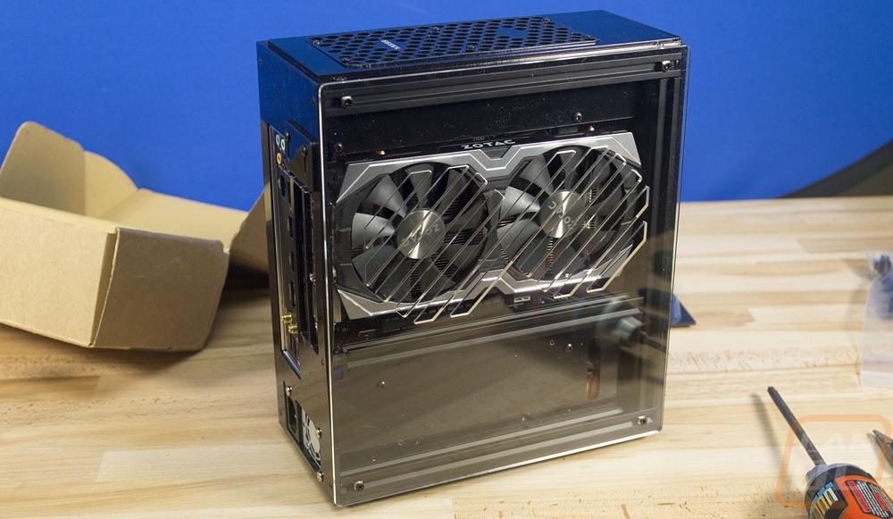
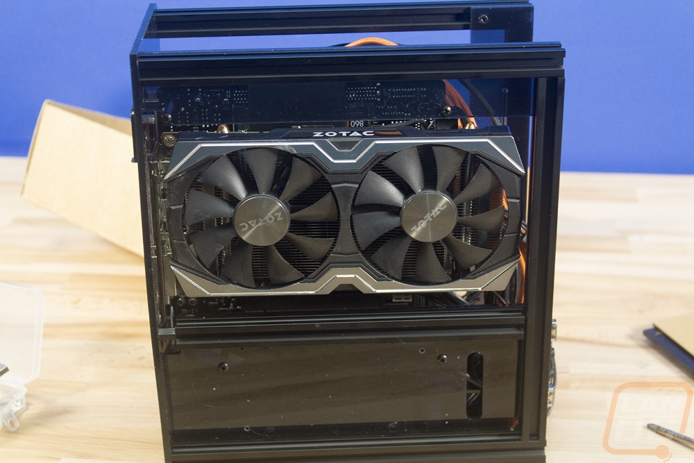
So for video card support, the A30 does have a limited amount of room. For starters, you only have 2 slots, not any extra room for the 2.5 slot cards. But that’s not much of an issue because you can really only fit the ITX length cards. GEEEK lists full-size GPU support but really they support 211mm normally and 228mm if you don’t use the front mounted 2.5 inch hard drive bracket. Well, I decided to use our Zotac GTX 1060 AMP! Edition, it is a little longer than the ITX form factor cards at 210mm but it should work. That said I don’t know how you fit anything longer, even without the bracket. I actually broke the shroud off of our card when trying to slip it into the A30. Once installed the slide down hold down bracket isn’t really ideal. I found that our card still moved around a little. I may actually replace it with a right-angled metal hold down that I could at least use two screws and bolts to lock the card from moving around.
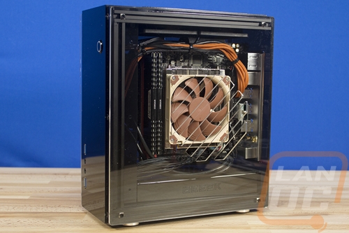
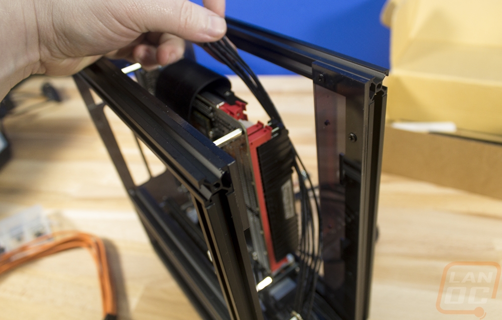
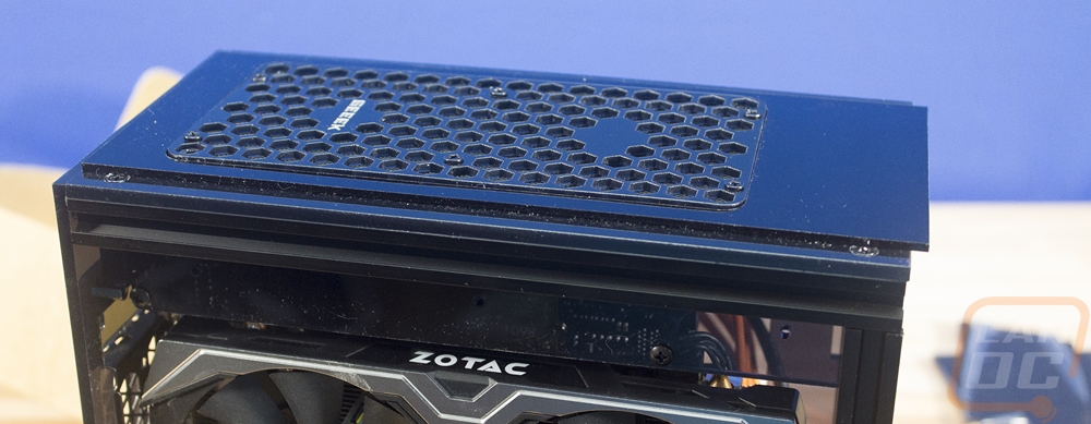
With the video card installed I could finally install the top panel into the case. This is basically when we finally start to see the A30 close-up and become a real enclosure. It’s finally growing up! lol
Next, you work on the front panel, but before you do that you have to install the power switch. I also went ahead and ran the wire over and plugged it in. Then from there, you can install the case. This might be the easiest of all of the panels to install. There are six mounting points but only two of them use those hard to work with extrusion clamps. The top and bottom screws are all going into the ends of the extrusions. So I fought with the two middle screws first then popped the rest together.
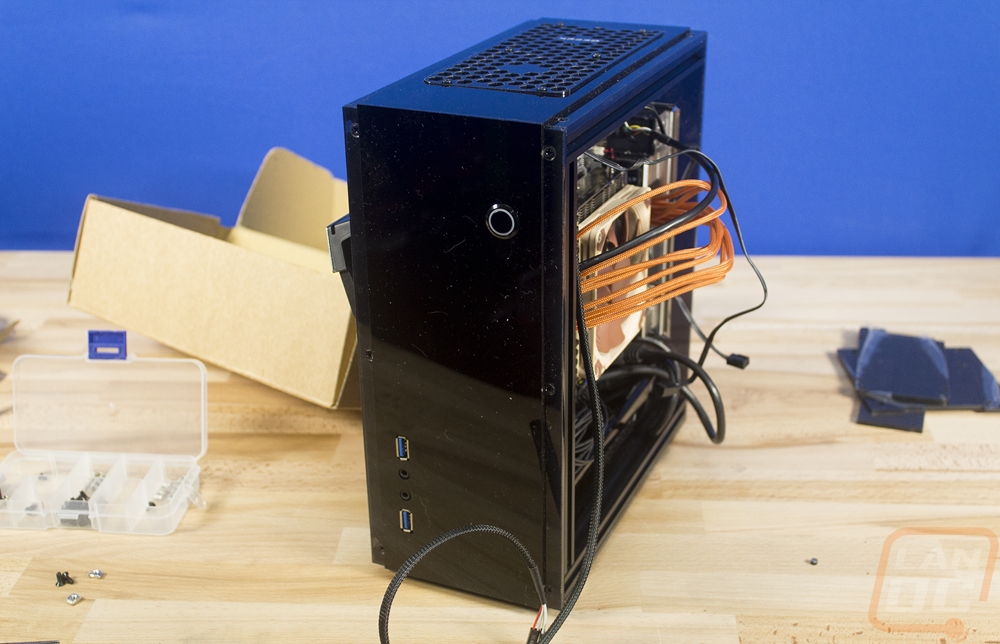
Before buttoning up the side panels I did finally go back through the wiring to clean it up a little. With the Gigabyte board, my wiring is going to be a lot different than everyone elses, but I found that I could bundle up a lot of the wires going up to the top then to the left and it looked good. The USB 3.0 cable though was a big challenge to keep it looking good. Then when I got it looking nice it would push down on the PSU cover that I didn’t hold down and tilt it slightly. Going with the optional flexible USB 3.0 cable that they now have would make a big difference here. Plus it would match the PSU cables. Once everything is cleaned up, installing the side panels isn’t too bad. Unlike the other panels with the t-slot nuts, these are transparent panels. So you can see what you are doing and even if one slips out you can kind of finesse them back into place.