Board Layout and Pictures
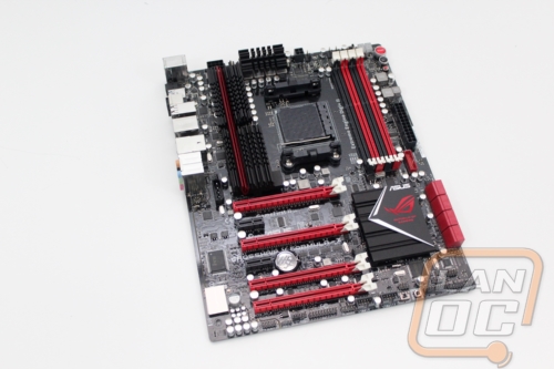
Much like the packaging, with the Crosshair V Formula-Z being an ROG motherboard it does have the full black and red theme going on. Being a little bit of an older board design its overall styling isn’t really what we see on the newer boards. That means the headsinks have the older more aggressive styling. Beyond that it is a full ATX board packed full of features, so lets take a closer look to see what it is all about.
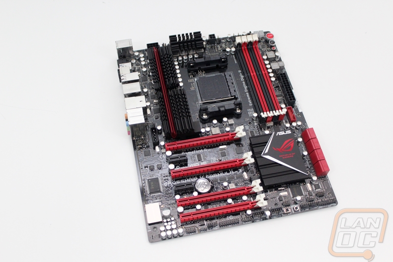
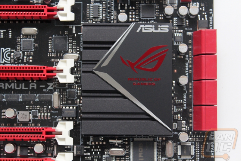
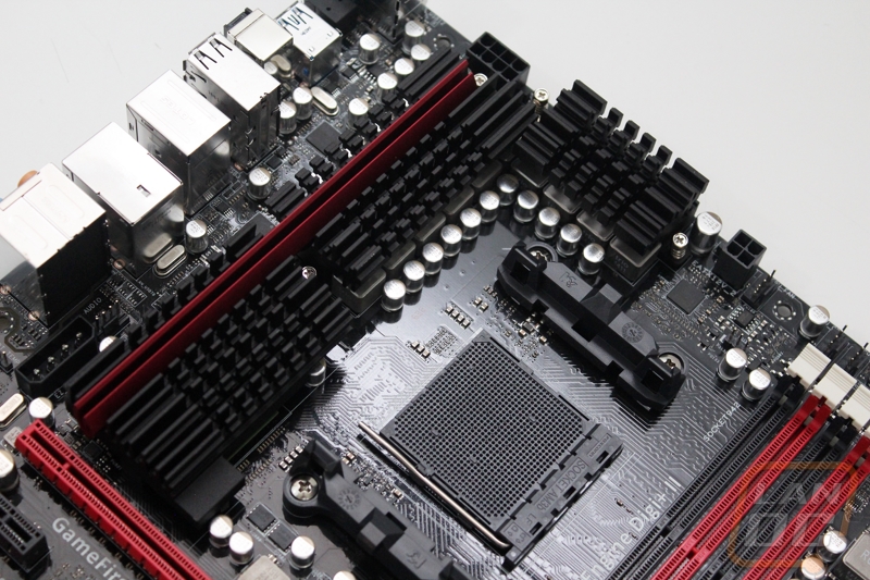
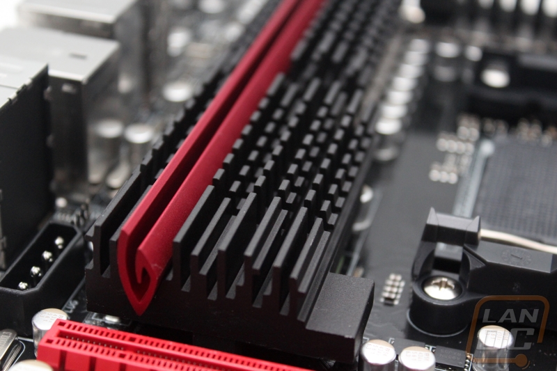
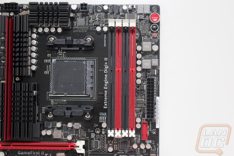
To start things off, let’s take a look at all of the cooling on the Crosshair Formula-Z. Around the CPU socket we have two heatsinks, the smaller of the two along the top with a long heatsink that runs the full height of the CPU socket area and is longer than the RAM slots. Those two heatsinks have a single red anodized piece and the rest are anodized black. For the chipset heatsink Asus kept things low profile to prevent ay clearance issues with video cards. That heatsink has both the Asus and ROG logos on them along with a machined V shape.
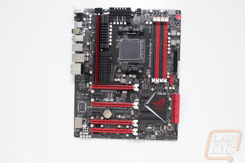
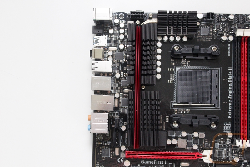
Starting up in the top left corner we have a few things going on. For starters, behind the rear I/O panel we have a Molex power connection to give additional power to the PCI slots for when you are running and overclocking quad card setups. Next to it is our first 4-pin PWM fan header. Up along the top we have an 8-pin power connection for the CPU and then a second 4-pin for when you are overclocking to supply the CPU with even more power. Next to the four pin is the 4-pin PWM fan header for the CPU and then two more up in the top right corner of the photo. That’s makes a total of four so far.
Over on the top right we have the four DDR3 DIMMS taking up most of the room, two in red and two in black. Starting up along the top there is a small switch, this turns on slow mode to help when overclocking and you are having a hard time getting through the boot. The jumper just below it is for LN2 mode to help support the lower temperatures. Next we have the LED diagnostic readout, it’s interesting this is up on the top, they are normally down along the bottom of most boards. Next are the start/power and reset buttons, the start button has a racecar start button look to it. Next is the GO button, this will test and set reset the memory to a working speed when you are having problems. Down next to the RAM slots we have our 5th 4-pin PWM fan header as well as the 24-pin motherboard power connection. Slipped in next to the motherboard power is a set of test pads to test all of the motherboard voltages. Under the voltage pads are four small LEDs, these will help diagnose boot problems, the part of the board with an issue will be lit up. Lastly, we have a red USB 3.0 header.
Down in the bottom right corner we have 8 SATA 3 ports. Down along the bottom starting from the right we have the front panel connections. Next are two more 4-pin PWM fan headers putting us up to 7 now. Next is a small Direct Key button that loads you directly into the BIOS. Next is a small switch that turns on fast boot mode.
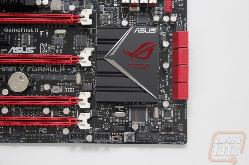
Over on the bottom left half there are two USB 3.0 headers up under the PCIe slots. Next is the TPM header and the TB Header. After that we have the eighth and final 4-pin PWM header, making for a crazy number of fan connections. Next is the front panel audio header, if you look close you can see that the PCB is split with a transparent resin between the main motherboard and the audio section. This helps isolate the SupremeFX II onboard audio to give the best possible audio performance. This isn’t up to the standard that the most recent SupremeFX chipsets with headphone amps and premium capacitors, but still better than most other AM3+ boards.
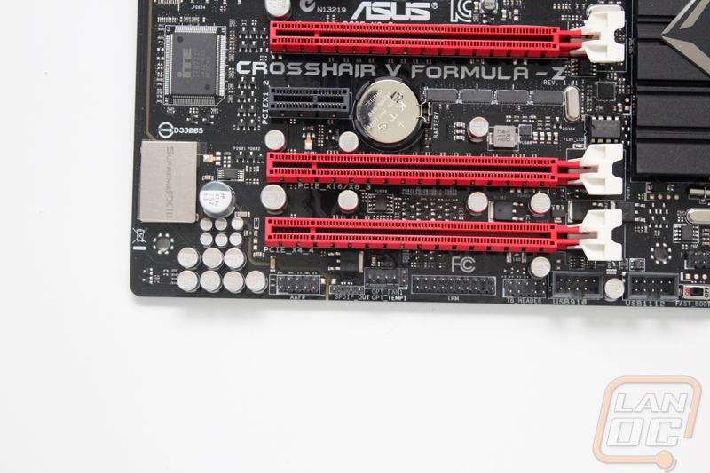
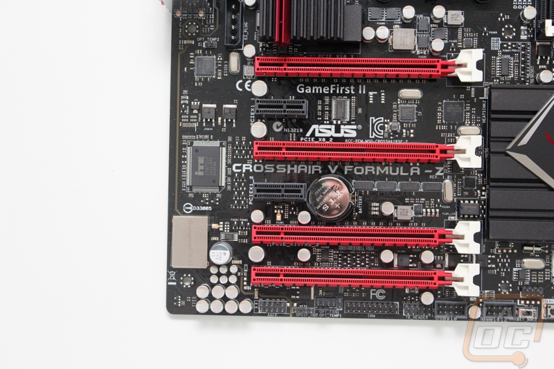
For PCI Express slots on the Crosshair you get four full length slots and two PCIe x1 slots. Of the four PCIe x16 looking slots, the bottom one is a full time x4 and the other three share bandwidth. You can run two as x16 slots or one x16 and two x8’s.
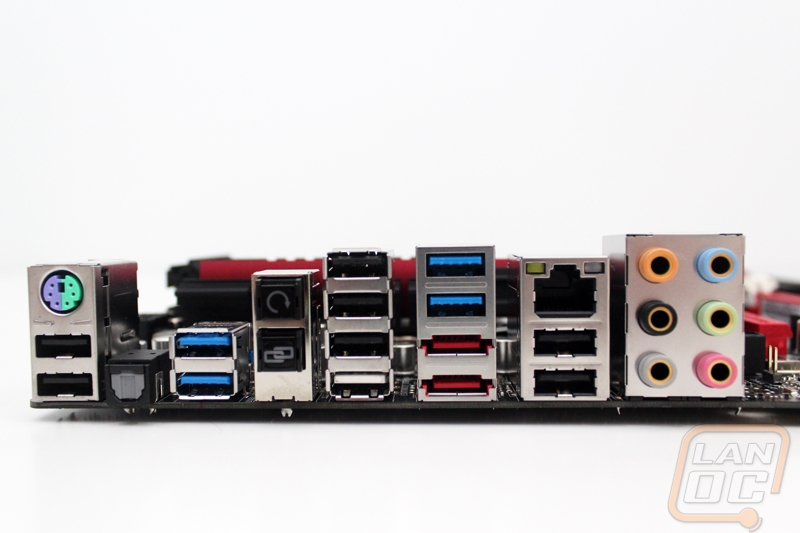
When we finally get around to the rear I/O panel I can see that Asus has packed the entire panel almost completely full. You get a total of 12 USB ports, four of those being USB 3.0. One of the ports doubles as the ROG Connect port as well, you can spot it because of its white color. For audio you get a six port audio setup as well as a S/PDIF connection over on the left side. Speaking of over on the left, just above the two USB 2.0 ports for your mouse and keyboard you have a PS2 connection for people who are looking for full NKRO on some keyboards and for older keyboards. I’m a little surprised that the Crosshair only gets one NIC, typically higher end boards have two, not that I ever need two. You do get an Intel 82574L NIC though. Then lastly, we have two buttons on the rear I/O panel. The top button is the SMOS reset button, giving you easy access to that without having to pull your side panel off. The other buttons is the ROG connect button.
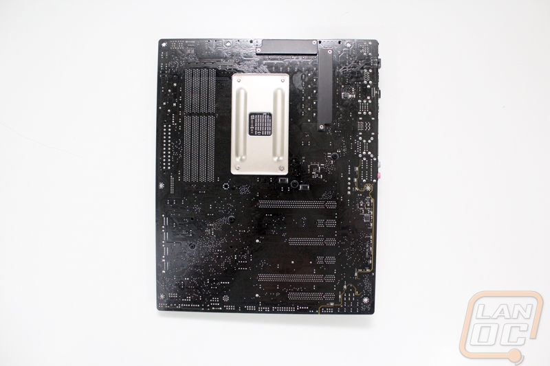
When we flip the Crosshair over, we can get a better look at the glossy black PCB that Asus went with. There are also three different backplates, two are for the motherboards heatsinks to keep them more secure and prevent damage to the board. The third is the larger one under the heatsink that supports the CPU heatsink mounts.