Board Layout
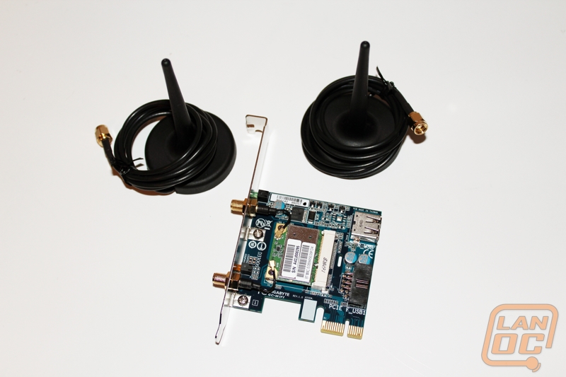
Here is a full shot of the GC-Wifi wireless card and both of its included wireless antenna’s. If you look close you can actually see that this is a standard wireless card designed for laptop and Mini ITX use that is running on an adapter card. What you don’t know just from looking at this photo is that this card also runs Bluetooth 4.0 using one of its two antennas’. You can tell the difference on the back of the card with different colored status LED’s and labels also. (wireless on top and BT on bottom). The card plugs into a 1x PCI Express slot but also requires an internal USB 2.0 connection. The wireless runs off of the PCI Express x1 connection while the Bluetooth runs on the USB.
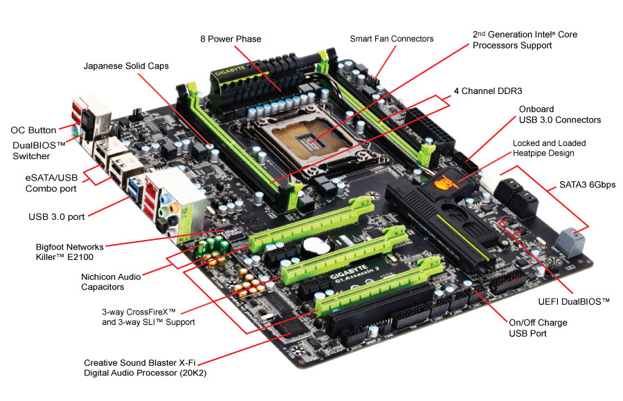
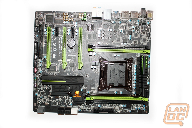
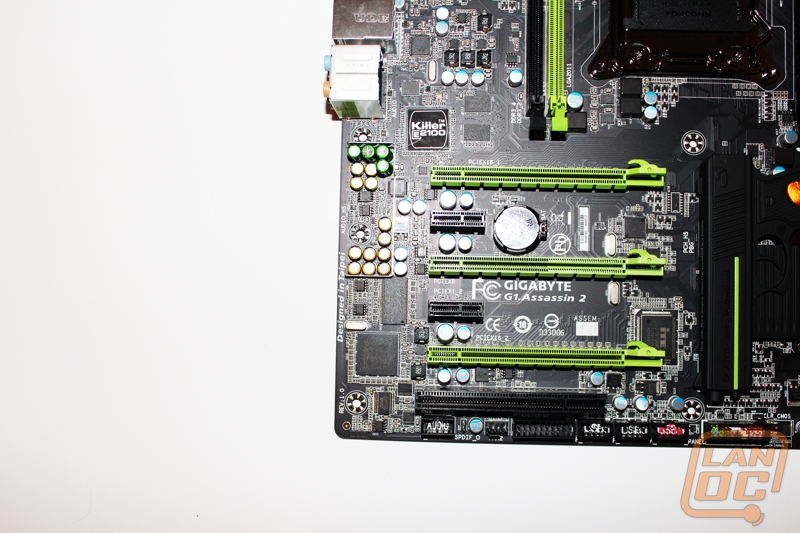
Here is an overall look at the Assassin 2, from here the Killer NIC and audio chipset really stand out. You can see that Gigabyte went with a flat black PCB for the board, it looks great and is complemented by the black and green PCI/DRAM sockets.
The best past about X79 boards like the Assassin 2 is the chipset/sockets additional CPU Lanes. This allows manufactures like Gigabyte to setup true triple SLI/Crossfire configurations without the extreme limitations that you would see with Sandy Bridge. The Assassin 2 slot breakdown is as follows
PCI Express x16
PCI Express x1
PCI Express x8 (x16 form factor)
PCI Express x1
PCI Express x16
Legacy PCI
As you can see you have triple SLI/Crossfire support or you can run dual GPU’s while still leaving open one of the PCI Express x1 slots for using the included Wifi/Bluetooth module.
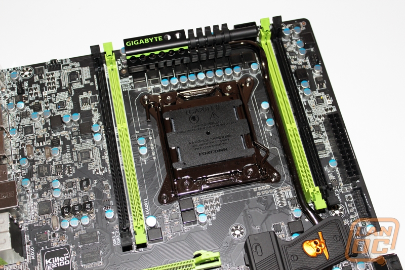
One of the most debatable features of the Assassin 2 is Gigabytes choice to go with only four dim slots when a lot of other full feature boards come with 8 dimm slots. Personally I don’t have any problem with it, I myself would only end up running a 16Gb quad channel kit both because I don’t need any more than that and I would rather have the overclocking headroom. Those are both the same reasons that Gigabyte went with just four dim slots. The idea being that gamers won’t need over 32 Gigs of ram, leaving 8 dimm setups just for workstation boards.
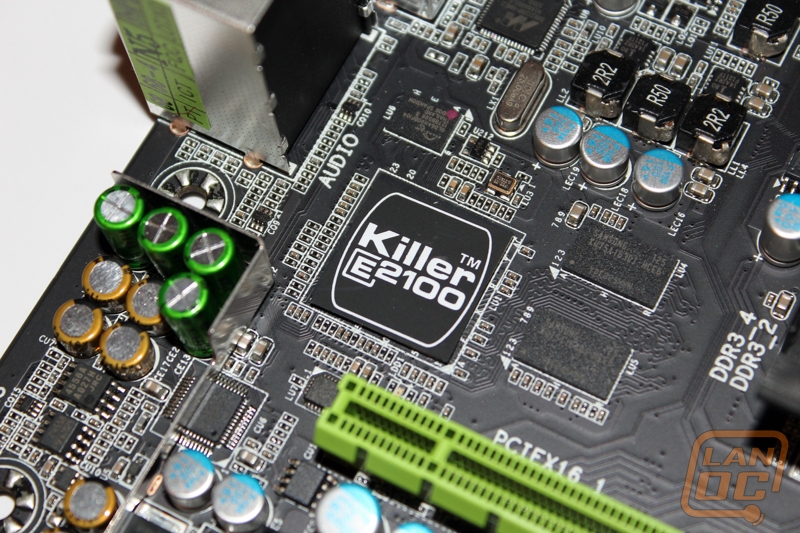
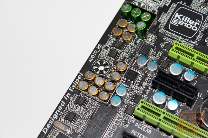
It may come as no surprise to those of you who have seen other G1 Killer motherboards like the original Assassin but the Bigfoot Networks (qualcomm) e2100 NIC is built right into the Assassin 2. You can spot the NPU just above the top PCI Express x16 slot with the bright E2100 logo on it. Just next to the NPU is also the built in dedicated DDR. This goes along with what Gigabyte is calling “Super Speed” , helping you avoid the windows network stack all together to give the best gaming experience possible.
Just like the built in e2110 NIC, Gigabyte has also integrated the Soundblaster Digital Audio Processor (20k2) along with its own 128Mb of dedicated memory also. Even more interesting is the use of high end Nichicon caps (the green and gold caps) along with the shielding placed around the caps to try to prevent any interference from the rest of the motherboard. Along with the caps, if you look close you can actually see all five of the built in high capacity amplifiers, most interesting of them all are the front amplifiers. With front amplifiers pushing the front audio connections you will get crisper details and less distortion while using good headphones.
Moving to the top right corner of the Assassin 2 you can spot both the second 8 pin CPU connection and part of the 24 pin power connection. You also have a 4 pin PWM fan connection if needed.
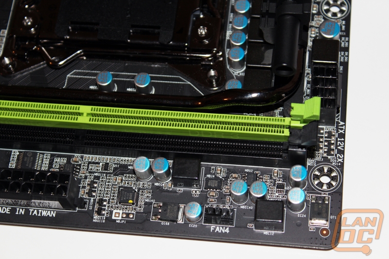
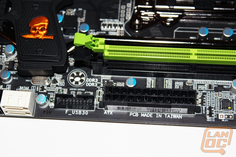
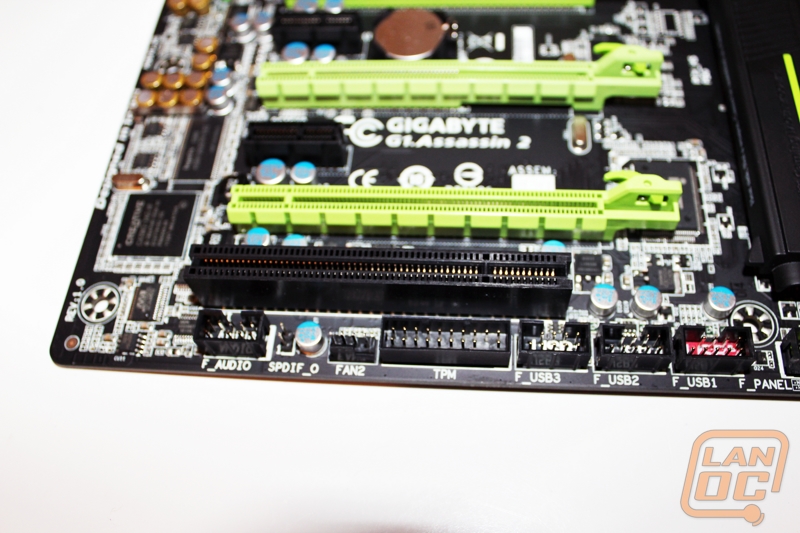
A little lower down we have full view of the 24 Pin connection along with an internal USB 3.0 header just under the main power connection.
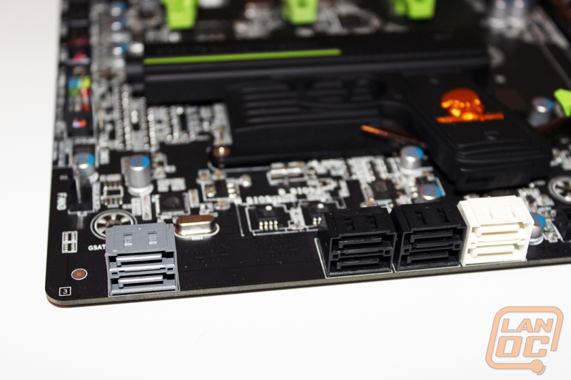
On the bottom right side of the Assassin 2 you have the SATA connections. It’s a little odd that Gigabyte placed two of the SATA ports down far apart from the others. You have a total of four SATA 2 ports and four SATA 3 ports with two of the SATA 6 ports running off of a Marvell 88SE9172 chip. There is a second Marvell 88SE9172 chip that also runs the two eSATA connections on the back of the I/O panel.
Starting on the right side of the bottom we have another PWM 4 pin fan header, our clear CMOS jumper (its right above the front panel connections), our front panel header, and three USB 2.0 headers with one being red in color for extra power for device charging.
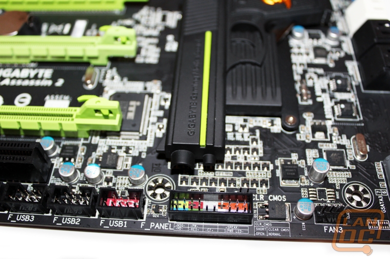
The left side of the bottom row has a TPM header, another PWM 4 pin fan header, and the front panel audio connection. It’s great to see Gigabyte putting the front panel header down at the bottom, in the past we would normally see it tucked in behind the rear I/O panel.
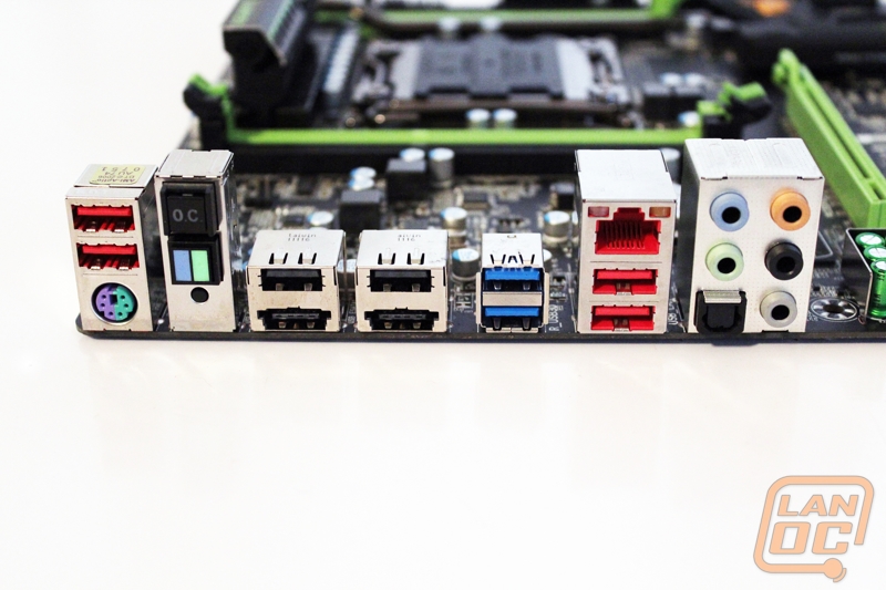
The rear I/O panel has everything you need and nothing you don’t. Gigabyte kept it fairly simple. Starting from the left you have two USB 2.0 connections for plugging in your mouse and keyboard along with a dual use PS2 connection in case you would like to hookup an old IBM keyboard or similar. The next stack has Gigabytes OC button and a dual BIOS switching buttons. Next you have two matching eSATA/USB combo ports along with two normal USB 2.0 ports with them/ The Two blue USB ports are USB 3.0. Next you have two red USB 2.0 ports that provide extra power for charging your devices when needed. On that same stack you have the 10/100/1000 Killer NIC port. Last but not least you have the audio connections. From the back here you can’t even tell that Gigabyte has included that Creative Sound Blaster X-Fi DAP.
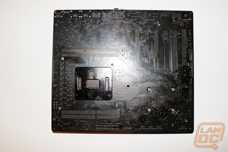
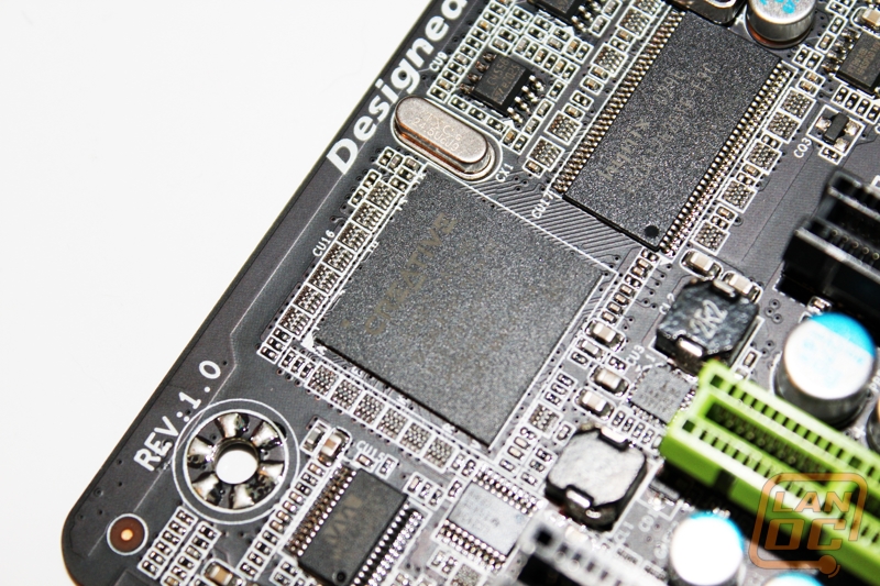
A quick peak at the underside of the board shows off that nice black PCB and you can see all of the mounting points for Gigabytes cooling. It’s nice to see that most of the heatsinks are attached by screws on the underside rather than plastic push pins.