Board Layout
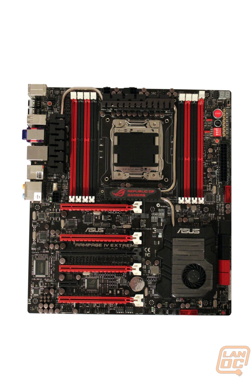
The overall look of the Rampage IV is amazing and a little intimidating. The eight DIMM slots, 5 PCI Express slots and active cooling are all eye catching. Even better is the red and black theme all across the board.
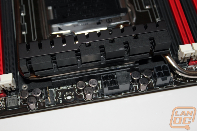
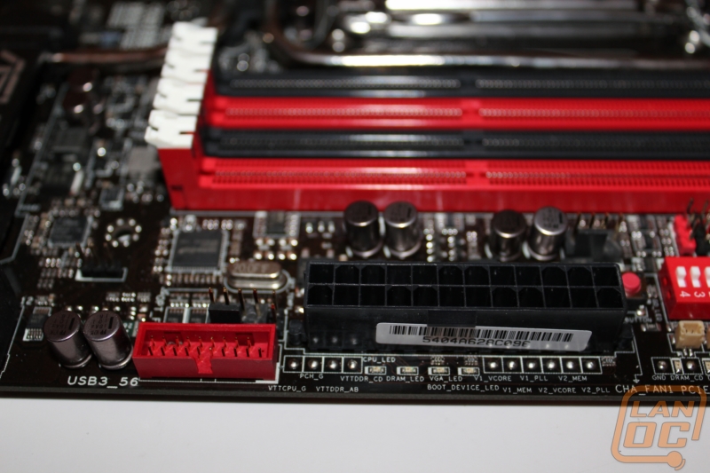
Starting directly at the top of the board you can see all of the CPU connections needed for the Rampage IV. You have a total of one 8 pin and one 4 pin although they have half of the 8 pin covered meaning you will only need one 8 pin unless you are planning on pushing the power requirements for the CPU. In this photo you can also see the CPU fan header, it’s a little hidden and hard to see.
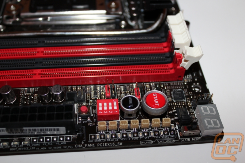
This one photo alone is a great example of how much ASUS packed into the Rampage IV. Here in the top right corner of the board you can see they have placed the LED readout right next to one of many 4 pin fan headers (one of two in this photo alone). Below the LED there is a switch for slow mode, specifically designed to allow someone doing extreme overclocking to slow the overclock back down to cool things down temporally or to help with booting while overclocking. Behind the Slow mode switch there is a small jumper that will turn on LN2 mode, to give better overclocking when working at less than -10 degree’s Celsius.
Moving down you have the sports car inspired Start button to turn your PC on and reset button. Between the Start button and the ram slots you have six sets of pin headers for VGA Hot-Wire, a on board solution that gives you full adjustability when overclocking video cards. This is completely unique to the Rampage motherboard as a way to replace the use of variable resisters and give you on the fly adjustments using the Rampage’s multiple overclocking solutions.
To the right of the start buttons you have seven small connections for use with Asus’s Probelt connectors that give you leads to connect your multi meter to for accurate voltage readings on each rail. Along with that you will see a series of very small LED’s that Asus calls its Voltiminder LED II. These LED’s are in place to give an overclocker an idea of where their overclocked failed. They use Voltage Programming Indicators, which, when stopped at a particular LED indicated that specific voltage setting is the cause for the failed overclock.
Just below the reset button there is a bright red box with four switches placed on it. Along the side of that there are four matching LED’s. The four switches each turn off a PCIe x16 slot. The reason for this is to be able to quickly troubleshoot a failed VGA card while overclocking without having to pull all of your cards out, something that when overclocking with LN2 can be a major pain.
Also in this photo is something right out of the movie gone in 60 seconds, the go button. This is yet another overclocking feature packed into the Rampage. The idea behind the go button is that you configure an overclocking profile in the BIOS and set it to the go button. This allows you to boot up your PC and then push the button when you are ready to go with the overclock.
Moving a little farther down the right side of the board you can see the 24 pin power connector. Alongside you have 10 small dots used for checking current PSU voltages. In the middle you have four LED’s, this is Asus's QLED feature. QLED helps you troubleshoot booting issues by leaving the led on in the event there is an issue with any of them during post. You can spot another four pin fan header just above the red internal USB 3.0 header. Just to the right of the fan header in this photo is also a two pin thermal probe connection.
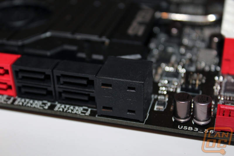
This large box with four connections could be a little puzzling to some. This is what Asus is calling Subzero Sense. That have integrated two Type-K Probe digital thermometers onboard. This gives you the ability to keep a close eye on your temperatures with accuracy and on the fly when doing extreme overclocking with LN2.
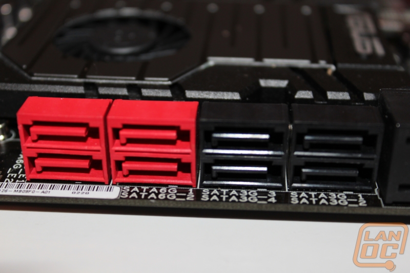
For SATA connections you have a total of eight internally. Of those eight, four (the black ports) are running at SATA2 speeds. The other four (red) ports are running at SATA3 speeds. Two things are tricky here, first they have labeled the ports as SATA6G and SATA3G, if you were looking for a SATA 3 connection this could be a little confusing. Second on the SATA 3 ports you have to be careful to select the correct ports when configuring a RAID. The SATA6G_1 and 2 ports run on the X79 chipset just like the SATA 2 ports. The Two SATA6G_E1 and 2 ports on the other hand run on an Asmedia ASM1061. That means you can run two SATA 3 RAID’s but you can’t mix them.
Down in the bottom right corner starting on the right you have a red button similar to the go button, but this button switches between the two on board BIOS’s. This is helpful especially if you managed to mess up a BIOS reflash. Next you have all of the front panel connections. The Front panel connections are lebled below the header but don’t have the easy to use color coding that we have seen on other boards. This is where Asus’s Q connector’s come into play giving you an easy way to plugin and unplug when needed.
The red header is the Rampage’s second internal USB 3.0 header and its sitting next to two more USB 2.0 headers. Last in this photo on the left side is yet another four pin fan header, these things are all over!
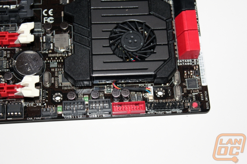
Moving to the bottom left side of the board and ignoring the PCI slots (for now). You have two BIOS chips, two more four pin fan headers, and the front panel audio header. In between the PCI slots they have tucked in the BIOS battery, you won’t be trying to get to it with three cards installed, nor will you be getting to any of the headers mentioned before when running four dual slot video cards. Tucked in between the two fan headers you have a second thermal probe header also. The two BIOS chips allow overclockers to run two fully independent versions of Asus's UEFI BIOS. This allows you to push the limits with one and switch back to a known good configuration at any time for example. There are small LED’s below each showing what BIOS you are currently running, when you push the switch BIOS button you will see it jump between the two.
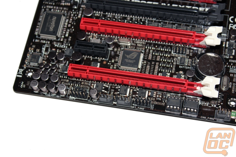
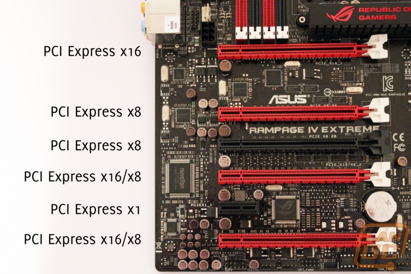
Here is the breakdown of the PCI slots for the Rampage IV. Nomatter how many video cards you run the top slot will always run as a x16 slot. If running two cards (using the top slot and one of the two slots labeled x16/x8) you will have two x16 slots running x16-x16. For a three card SLI or Crossfire you will have x16-x8-x8. And for those who are going to run four video cards, your configuration will be x16-x8-x8-x8. There is also another PCI Express slot in black that will also run x8 if needed, all of the typical video card slots have been colored in red. Last but not least you also have a PCI Express x1 slot tucked down at the bottom.
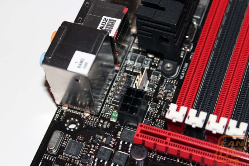
Just above the PCI slots and between the rear I/O and the memory you have a few connections buried away. The connection on the left that looks like a USB header is specifically for use with the OC Key. This allows it to be plugged in through a hole in the I/O panel. The other two connections are for additional power to the motherboard when overclocking. The six pin connection gives extra power to the PCI lanes and the four pin EZ Plug gives added power to the DRAM. Using both ports not only gives both power but opens up extra power on the 24 pin to be used toward the CPU during overclocking.
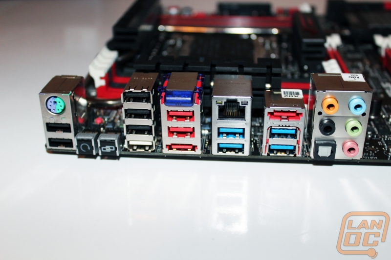
Here is the Rampage IV’s rear I/O panel. You have your standard audio connections along with an optical connection. You have a total of twelve USB connections of various types. Four are USB 3.0 and labeled in blue. Two provide extra power and are colored in red. Five are black and color and are standard USB 2.0 ports with no additional power. And then there is one single white power that is used when running BIOS updates. During standard use this port doubles as a normal USB 2.0 port. In addition all of the USB 3.0 ports support ASUS new USB3 Boost implementation offering improved performance for both USB2 and USB3 devices!
You also end up with one legacy PS2 port. As an added feature Asus has included Bluetooth, just like every other board in their lineup. You also have two eSATA connections. There are two buttons on the rear I/O panel. One functions as a control button for ROG connect and also as a way to turn on the OC Key when using it. That same button is also used for USB BIOS Flashback, Asus's exclusive way of allowing you to update your BIOS quickly and easily even with no CPU or RAM in the PC. The Second button is an easy to reach Clear CMOS button. Saving the best for last I was impressed with the inclusion of the Intel Gigabit Network card on the Rampage IV, considering all of the features packed into the board most manufactures would have gone with a cheaper solution but Asus didn't compromise.
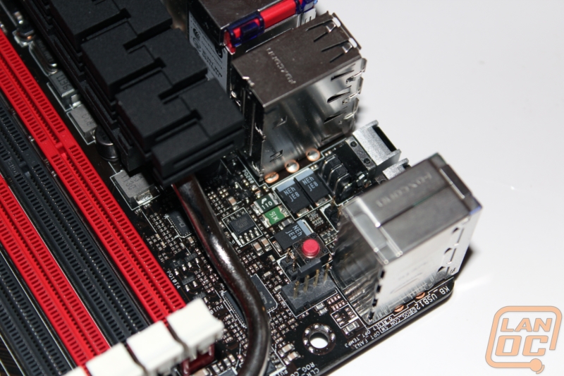
In the top right corner you have a few small headers including fan header number six. Just behind the I/O panel buttons there is a small two pin header. This is used as a second way to control ROG connect, any momentary switch wired to this will allow you to turn this on and off as needed while overclocking.
The other two pin connection in this photo is our third and final thermal probe header. The small red button in the photo is called the Q-reset button. This is for when the LN2 jumper doesn’t work and your CPU can’t resume function. It cuts power to the CPU and helps recover from a frozen situation.
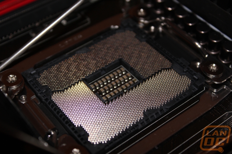
A nice shot of the LGA 2011 socket.